Fuel Injection Timing Correction Amount; Bearing Case Cover; different. Make sure that you use the correct one at the- Page 220
Kubota L3560 Owners Manual
Table of Contents
ENGINE
L3560, L4060, L4760, L5060, L5460, L6060, WSM
1-S73
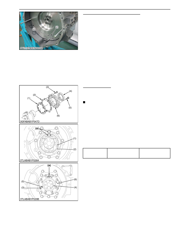
Fuel Injection Timing Correction Amount
The difference A between the top dead center mark (1) and the
crank position sensor top dead center detection position mark (2) is
the correction amount for fuel injection timing.
Calculate the correction value referencing the following and
using a diagnostics tool, overwrite the injection timing correction
amount in the "data overwrite/confirmation".
(Remarks)
• 1 mm = 360 ° / (Flywheel Diameter × π)
(For example)
FD = 300 mm → 1 mm = 0.38 °
Correction amount (CA) = 0.38 × A (mm)
• If the crank position sensor top dead center detection position is
in front of top dead center, enter a negative value.
• If the crank position sensor top dead center detection position is
in back of top dead center, enter a positive value.
9Y1210824ENS0064US0
Bearing Case Cover
1. Remove the mounting screws of the bearing case cover. First,
remove inner screws (5) and then external screws (3).
2. Remove the bearing case cover (6).
IMPORTANT
• The length of inner screws (5) and external screws (3) are
different. Make sure that you use the correct one at the
correct position.
(When reassembling)
• Attach the bearing case gasket (1) and the bearing case cover
gasket (2) in the correct directions.
• Put the casting mark
"UP"
of the bearing case cover (6)
upward, then install the bearing case cover.
• Apply a thin layer of engine oil to the oil seal.
Then install the oil seal not to come off the lip.
• Tighten the mounting screws of the bearing case cover with an
equal force on the diagonal line.
9Y1210824ENS0065US0
(1) Mark for Top Dead Center
(2) Mark of Crank Position Sensor Top
Dead Center Detection Position
A: Correction amount (mm)
Tightening torque
Mounting screw of bearing
case cover
24 to 27 N·m
2.4 to 2.8 kgf·m
18 to 20 lbf·ft
(1) Bearing Case Gasket
(2) Bearing Case Cover Gasket
(3) Mounting Screw of Bearing Case
Cover
(4) Oil Seal
(5) Mounting Screw 1 of Bearing Case
Cover
(6) Bearing Case Cover
(a) Upside
KiSC issued 03, 2016 A
Detailed Information for Kubota L3560 Owners Manual
Lists of information found in Kubota L3560 Owners Manual - Page 220
- 1. Remove the mounting screws of the bearing case cover.
- 2. Remove the bearing case cover (6).
- 2.4 to 2.
- 1 mm = 360 ° / (Flywheel Diameter × π) (For example) FD = 300 mm → 1 mm = 0.
- If the crank position sensor top dead center detection position is in front of top dead center, enter a negative value.
- If the crank position sensor top dead center detection position is in back of top dead center, enter a positive value.
- The length of inner screws (5) and external screws (3) are different.
- Attach the bearing case gasket (1) and the bearing case cover gasket (2) in the correct directions.
- Put the casting mark "UP" of the bearing case cover (6) upward, then install the bearing case cover.
- Apply a thin layer of engine oil to the oil seal.
- Tighten the mounting screws of the bearing case cover with an equal force on the diagonal line.