Cylinder Head Flaw; Valve Recessing; Clearance between Valve Stem and Valve Guide- Page 224
Kubota L3560 Owners Manual
Table of Contents
ENGINE
L3560, L4060, L4760, L5060, L5460, L6060, WSM
1-S77
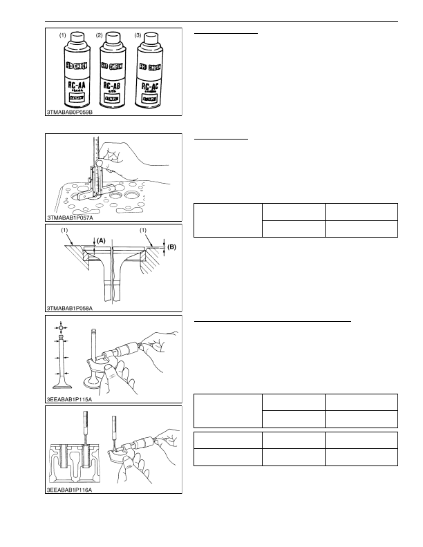
Cylinder Head Flaw
1. Prepare an air spray red check.
2. Clean the surface of the cylinder head with detergent (2).
3. Apply some red permeative liquid (1) on the cylinder head
surface. After you apply, do not touch it for 5 to 10 minutes.
4. Clean away the red permeative liquid on the cylinder head
surface with detergent (2).
5. Apply the white developer (3) on the cylinder head surface.
6. If you found a red flaw, replace the cylinder head.
9Y1210824ENS0070US0
Valve Recessing
1. Clean the cylinder head surface, valve face and valve seat.
2. Set the valve into the valve guide.
3. Measure the valve recessing with a depth gauge.
4. If the measurement is more than the allowable limit, replace the
valve.
5. If it stays more than the allowable limit after you replace the
valve, replace the cylinder head.
9Y1210824ENS0071US0
Clearance between Valve Stem and Valve Guide
1. Remove carbon from the valve guide section.
2. Measure the valve stem O.D. with an external micrometer.
3. Measure the valve guide I.D. with a small hole gauge, and
calculate the clearance.
4. If the clearance is more than the allowable limit, replace the
valves.
5. If the clearance stays more than the allowable limit, replace the
valve guide also.
9Y1210824ENS0072US0
(1) Red Permeative Liquid
(2) Detergent
(3) White Developer
Valve recessing
Factory specification
0.65 to 0.85 mm
0.026 to 0.033 in.
Allowable limit
1.20 mm
0.0472 in.
(1) Cylinder Head Surface
(A) Recessing
(B) Protrusion
Clearance between
valve stem and valve
guide
Factory specification
0.040 to 0.070 mm
0.0016 to 0.0027 in.
Allowable limit
0.10 mm
0.0039 in.
Valve stem O.D.
Factory specification
7.960 to 7.975 mm
0.3134 to 0.3139 in.
Valve guide I.D.
Factory specification
8.015 to 8.030 mm
0.3156 to 0.3161 in.
KiSC issued 03, 2016 A
Detailed Information for Kubota L3560 Owners Manual
Lists of information found in Kubota L3560 Owners Manual - Page 224
- 1. Prepare an air spray red check.
- 2. Clean the surface of the cylinder head with detergent (2).
- 3. Apply some red permeative liquid (1) on the cylinder head surface.
- 4. Clean away the red permeative liquid on the cylinder head surface with detergent (2).
- 5. Apply the white developer (3) on the cylinder head surface.
- 6. If you found a red flaw, replace the cylinder head.
- 1. Clean the cylinder head surface, valve face and valve seat.
- 2. Set the valve into the valve guide.
- 3. Measure the valve recessing with a depth gauge.
- 4. If the measurement is more than the allowable limit, replace the valve.
- 5. If it stays more than the allowable limit after you replace the valve, replace the cylinder head.
- 1. Remove carbon from the valve guide section.
- 2. Measure the valve stem O.
- 3. Measure the valve guide I.
- 4. If the clearance is more than the allowable limit, replace the valves.
- 5. If the clearance stays more than the allowable limit, replace the valve guide also.
- 1.20 mm 0.
- 7.960 to 7.
- 8.015 to 8.