Measuring Angular Deviation between Crankshaft TDC and Crank Position Sensor Detected TDC; Confirmation of Top Dead Center- Page 218
Kubota L3560 Owners Manual
Table of Contents
ENGINE
L3560, L4060, L4760, L5060, L5460, L6060, WSM
1-S71
Measuring Angular Deviation between Crankshaft TDC and Crank Position Sensor Detected TDC
IMPORTANT
• Perform this correction every time the crank shaft or flywheel is replaced.
9Y1210824ENS0061US0
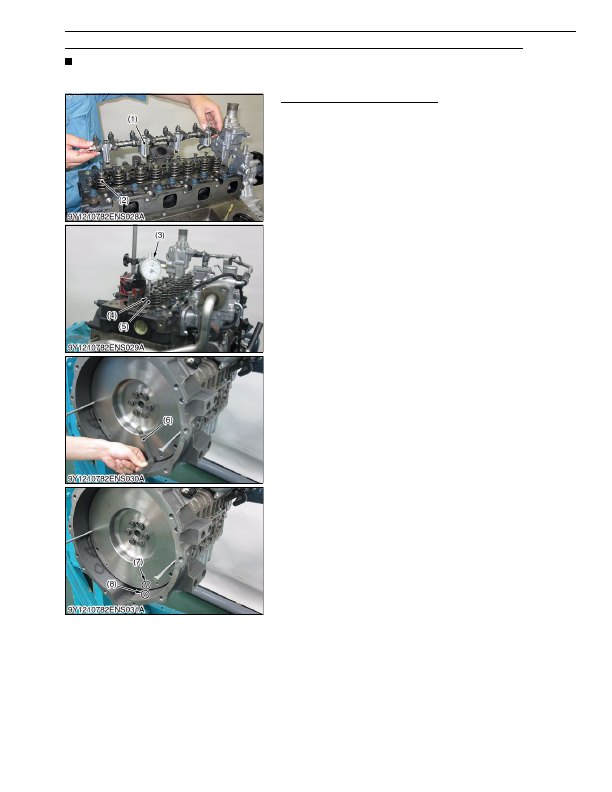
Confirmation of Top Dead Center
1. Remove the rocker arm (1). (See disassembling and
assembling)
2. Align the #4 piston with top dead center and remove the valve
spring (2) of the #4 cylinder
3. Insert an O-ring (4) to prevent the exhaust valve (5) from falling
into the cylinder and position the dial gauge (3) at the tip of the
valve.
4. While turning the flywheel to the left, the largest deflection of the
needle on the gauge indicates top dead center so stop the
flywheel in this position and set a tri-square (6) as indicated in
the diagram and place a top dead center mark (7) on the
reference line (8) and flywheel on the engine body side. Note, in
the case the flywheel is turned too far, return it by turning to the
right and start over.
9Y1210824ENS0062US0
(1) Rocker Arm
(2) Valve Spring
(3) Dial Gauge
(4) O-Ring
(5) Exhaust Valve
(6) Tri-square
(7) Mark for Top Dead Center
(8) Reference Line
KiSC issued 03, 2016 A
Detailed Information for Kubota L3560 Owners Manual
Lists of information found in Kubota L3560 Owners Manual - Page 218
- 1. Remove the rocker arm (1).
- 2. Align the #4 piston with top dead center and remove the valve spring (2) of the #4 cylinder 3.
- 4. While turning the flywheel to the left, the largest deflection of the needle on the gauge indicates top dead center so stop the flywheel in this position and set a tri-square (6) as indicated in the diagram and place a top dead center mark (7) on the reference line (8) and flywheel on the engine body side.
- Perform this correction every time the crank shaft or flywheel is replaced.