Shift Levers; A: Fork Rod Groove; Release Hub and Clutch Lever- Page 378
Kubota L3560 Owners Manual
Table of Contents
TRANSMISSION
L3560, L4060, L4760, L5060, L5460, L6060, WSM
3-S59
Shift Levers
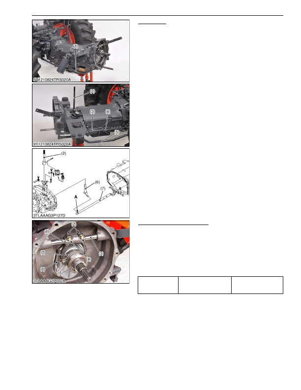
1. Disconnect the brake rods (1), (5).
2. Tap out the spring pins (3) of main shift rod 1 (4).
3. Remove the shuttle shift arm stopper mounting screw, and then
pull the shuttle shift shaft (2) with shuttle shift arm (6) up.
(When reassembling)
• Tap in the spring pins (3) so that their split portion may face
forward.
• When reassembling the shuttle shift arm (6) to the shuttle fork
rod (7), be sure to install it to the groove
"A"
.
9Y1210824TRS0011US0
Release Hub and Clutch Lever
1. Draw out the clutch release hub (7) and the release bearing (5)
as a unit.
2. Remove the release fork setting screws (4) and fork keys (2).
3. Draw out the clutch lever (3) to remove the release fork (1).
(When reassembling)
• Make sure the direction of the release fork (1) is correct.
• Inject grease to the release hub (7).
• Be sure to set the snap pins (6).
9Y1210824TRS0012US0
(1) Brake Rod
(2) Shuttle Shift Shaft
(3) Spring Pin
(4) Main Shift Rod 1
(5) Brake Rod
(6) Shuttle Shift Arm
(7) Shuttle Fork Rod
A: Fork Rod Groove
Tightening torque
Release fork setting screws
24 to 27 N·m
2.4 to 2.8 kgf·m
18 to 20 lbf·ft
(1) Release Fork
(2) Fork Key
(3) Clutch Lever
(4) Setting Screw
(5) Release Bearing
(6) Snap Pin
(7) Release Hub
KiSC issued 03, 2016 A
Detailed Information for Kubota L3560 Owners Manual
Lists of information found in Kubota L3560 Owners Manual - Page 378
- 1. Disconnect the brake rods (1), (5).
- 2. Tap out the spring pins (3) of main shift rod 1 (4).
- 3. Remove the shuttle shift arm stopper mounting screw, and then pull the shuttle shift shaft (2) with shuttle shift arm (6) up.
- 1. Draw out the clutch release hub (7) and the release bearing (5) as a unit.
- 2. Remove the release fork setting screws (4) and fork keys (2).
- 3. Draw out the clutch lever (3) to remove the release fork (1).
- 2.4 to 2.
- Tap in the spring pins (3) so that their split portion may face forward.
- When reassembling the shuttle shift arm (6) to the shuttle fork rod (7), be sure to install it to the groove "A" .
- Make sure the direction of the release fork (1) is correct.
- Inject grease to the release hub (7).
- Be sure to set the snap pins (6).