Main Shift Base; Separating Clutch Housing and Mid Case- Page 379
Kubota L3560 Owners Manual
Table of Contents
TRANSMISSION
L3560, L4060, L4760, L5060, L5460, L6060, WSM
3-S60
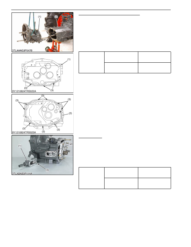
Separating Clutch Housing and Mid Case
1. Remove the clutch housing and mid case mounting screws and
nuts.
2. Separate the clutch housing (1) and mid case (2).
(When reassembling)
• Apply liquid gasket (Three Bond 1208C or equivalent) to joint
face of the clutch housing and mid case.
• Make sure to apply liquid gasket to elongated grooves (3) on the
mid case face and to those on the lower side of the clutch
housing face.
9Y1210824TRS0013US0
Main Shift Base
1. Remove the main shift base mounting screws.
2. Remove the main shift base (1) and main shift arm (3) as a unit.
(When reassembling)
• Apply liquid gasket (Three Bond 1208C or equivalent) to joint
face of the clutch housing case and main shift base.
• The main shift arm should be fitted on to the shift fork grooves
(2) after setting the shift forks to neutral position.
9Y1210824TRS0014US0
Tightening torque
Clutch housing and mid
case mounting nut
103 to 117 N·m
10.5 to 12.0 kgf·m
76.0 to 86.7 lbf·ft
Clutch housing and mid
case mounting screw
78 to 90 N·m
7.9 to 9.2 kgf·m
58 to 66 lbf·ft
(1) Clutch Housing
(2) Mid Case
(3) Elongated Groove
Tightening torque
Main shift base mounting
screw
24 to 27 N·m
2.4 to 2.8 kgf·m
18 to 20 lbf·ft
Main shift arm setting
screw
9.81 to 11.2 N·m
1.00 to 1.15 kgf·m
7.24 to 8.31 lbf·ft
(1) Main Shift Base
(2) Shift Fork Grooves
(3) Main Shift Arm
KiSC issued 03, 2016 A
Detailed Information for Kubota L3560 Owners Manual
Lists of information found in Kubota L3560 Owners Manual - Page 379
- 1. Remove the clutch housing and mid case mounting screws and nuts.
- 2. Separate the clutch housing (1) and mid case (2).
- 1. Remove the main shift base mounting screws.
- 2. Remove the main shift base (1) and main shift arm (3) as a unit.
- 12.0 kgf·m 76.
- 86.7 lbf·ft Clutch housing and mid case mounting screw 78 to 90 N·m 7.
- 9.2 kgf·m 58 to 66 lbf·ft (1) Clutch Housing (2) Mid Case (3) Elongated Groove Tightening torque Main shift base mounting screw 24 to 27 N·m 2.
- 2.8 kgf·m 18 to 20 lbf·ft Main shift arm setting screw 9.
- 11.2 N·m 1.
- 1.15 kgf·m 7.
- Apply liquid gasket (Three Bond 1208C or equivalent) to joint face of the clutch housing and mid case.
- Make sure to apply liquid gasket to elongated grooves (3) on the mid case face and to those on the lower side of the clutch housing face.
- Apply liquid gasket (Three Bond 1208C or equivalent) to joint face of the clutch housing case and main shift base.
- The main shift arm should be fitted on to the shift fork grooves (2) after setting the shift forks to neutral position.