Clutch Housing Bearing Holder; Shaft Assemblies; when pull out the bearing holder (5).- Page 381
Kubota L3560 Owners Manual
Table of Contents
TRANSMISSION
L3560, L4060, L4760, L5060, L5460, L6060, WSM
3-S62
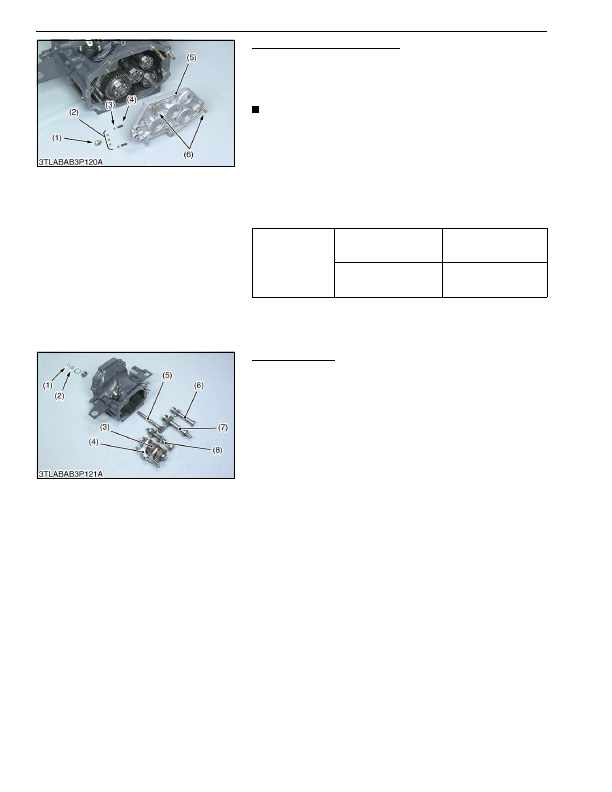
Clutch Housing Bearing Holder
1. Remove the three interlock balls (2) after removing the stopper
screw (1).
2. Pull out the clutch housing bearing holder (5) with using two jack
bolts (6).
NOTE
• Be careful not to fly out the detent balls (3) and springs (4)
when pull out the bearing holder (5).
(When reassembling)
• Tap in the clutch housing bearing holder (5) with plastic hummer
until contact to clutch housing case, and then tighten the screws
to specified torque.
• Install the three interlock balls (2) with a small amount of grease
to the clutch housing bearing holder (5) after setting the shift
forks and shift rods to the neutral position.
9Y1210824TRS0017US0
Shaft Assemblies
1. Remove the external snap ring (1) and collar (2).
2. Draw out the shaft assemblies (3), (5), (6), (7), (8).
9Y1210824TRS0018US0
Tightening torque
Clutch housing bearing
holder mounting screw
48 to 55 N·m
4.9 to 5.7 kgf·m
36 to 41 lbf·ft
Stopper screw
35 to 44 N·m
3.5 to 4.5 kgf·m
26 to 32 lbf·ft
(1) Stopper Screw
(2) Interlock Ball
(3) Detent Ball
(4) Spring
(5) Clutch Housing Bearing Holder
(6) Jack Bolt
(1) External Snap Ring
(2) Collar
(3) Counter Shaft Assembly
(4) Shift Rods
(5) 18T Gear Shaft Assembly
(6) Idle Shaft Assembly
(7) PTO Counter Shaft Assembly
(8) Main Gear Shaft Assembly
KiSC issued 03, 2016 A
Detailed Information for Kubota L3560 Owners Manual
Lists of information found in Kubota L3560 Owners Manual - Page 381
- 1. Remove the three interlock balls (2) after removing the stopper screw (1).
- 2. Pull out the clutch housing bearing holder (5) with using two jack bolts (6).
- 1. Remove the external snap ring (1) and collar (2).
- 2. Draw out the shaft assemblies (3), (5), (6), (7), (8).
- 4.9 to 5.
- 3.5 to 4.
- Be careful not to fly out the detent balls (3) and springs (4) when pull out the bearing holder (5).
- Tap in the clutch housing bearing holder (5) with plastic hummer until contact to clutch housing case, and then tighten the screws to specified torque.
- Install the three interlock balls (2) with a small amount of grease to the clutch housing bearing holder (5) after setting the shift forks and shift rods to the neutral position.