Differential Lock Shift Fork; Split Portion- Page 439
Kubota L3560 Owners Manual
Table of Contents
TRANSMISSION
L3560, L4060, L4760, L5060, L5460, L6060, WSM
3-S120
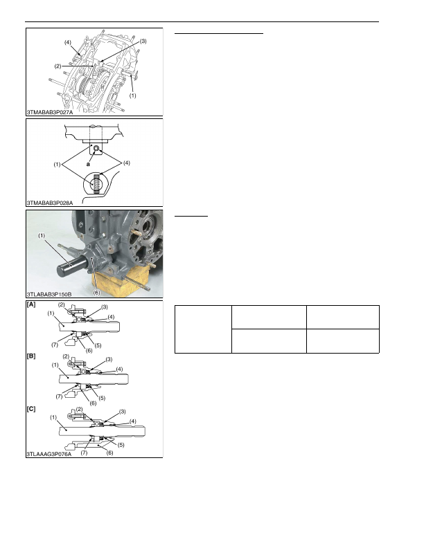
Differential Lock Shift Fork
1. Tap out the left side spring pin (4).
2. Remove the cotter pin and clevis pin (3).
3. Draw out the differential lock fork shaft (1) and remove
differential lock shift fork (2).
(When reassembling)
• Apply grease to the left and right oil seals on the transmission
case.
• Insert the clevis pin (3) from the top and install the washer and
cotter pin.
• Tap in the spring pin (4) so that its split portion
"a"
may face
outward as shown in the figure.
9Y1210824TRS0042US0
PTO Shaft
1. Remove the PTO shaft cover.
2. Remove the bearing case mounting screws, and draw out the
PTO shaft (1) with bearing case (6).
3. Remove the internal snap ring (2).
4. Top out the PTO shaft (1) to the front.
(When reassembling)
• If the lock nut (7) was removed, replace it with a new one. After
replacing, be sure to stake it firmly.
• Install the slinger (4) firmly.
• Apply grease to the oil seal (3) and install it, noting its direction.
9Y1210824TRS0124US0
(1) Differential Lock Fork Shaft
(2) DIfferential Lock Shift Fork
(3) Clevis Pin
(4) Spring Pin
a:
Split Portion
Tightening torque
Lock nut
150 to 190 N·m
15 to 20 kgf·m
110 to 140 lbf·ft
Bearing case mounting
screw
24 to 27 N·m
2.4 to 2.8 kgf·m
18 to 20 lbf·ft
(1) PTO Shaft
(2) Internal Snap Ring
(3) Oil Seal
(4) Slinger
(5) Oil Seal Collar
(6) Bearing Case
(7) Lock Nut
[A] L3560
[B] L4060, L4760
[C] L5460, L6060
KiSC issued 03, 2016 A
Detailed Information for Kubota L3560 Owners Manual
Lists of information found in Kubota L3560 Owners Manual - Page 439
- 1. Tap out the left side spring pin (4).
- 2. Remove the cotter pin and clevis pin (3).
- 3. Draw out the differential lock fork shaft (1) and remove differential lock shift fork (2).
- 1. Remove the PTO shaft cover.
- 2. Remove the bearing case mounting screws, and draw out the PTO shaft (1) with bearing case (6).
- 3. Remove the internal snap ring (2).
- 4. Top out the PTO shaft (1) to the front.
- 2.4 to 2.
- Apply grease to the left and right oil seals on the transmission case.
- Insert the clevis pin (3) from the top and install the washer and cotter pin.
- Tap in the spring pin (4) so that its split portion "a" may face outward as shown in the figure.
- If the lock nut (7) was removed, replace it with a new one.
- Install the slinger (4) firmly.
- Apply grease to the oil seal (3) and install it, noting its direction.