Rear Axle; Brake Case; Hydraulic Cylinders and Front Loader Control Valve- Page 435
Kubota L3560 Owners Manual
Table of Contents
TRANSMISSION
L3560, L4060, L4760, L5060, L5460, L6060, WSM
3-S116
Hydraulic Cylinders and Front Loader Control Valve
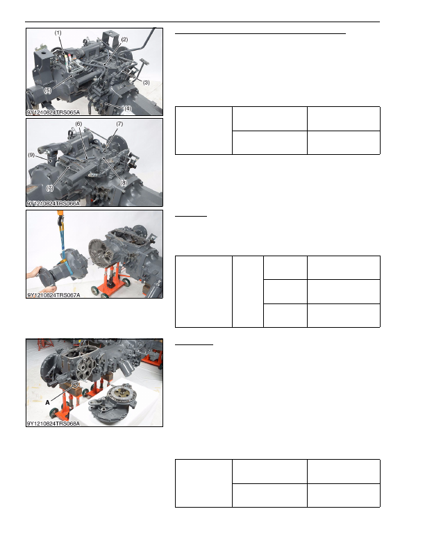
1. Remove the remote control hoses (1).
2. Remove the remote control valve (5) and pipe (2).
3. Remove the delivery pipe (3).
4. Remove the front loader control valve (4) with front loader
control valve bracket assembly.
5. Disconnect the hydraulic cylinder hoses (7) and return hoses (6)
at the rear hydraulic block (8).
6. Remove the pins, and remove the hydraulic cylinders (9).
9Y1210824TRS0117US0
Rear Axle
1. Separate the rear axle case from brake case.
(When reassembling)
• Apply liquid gasket (Three Bond 1208C or equivalent) to joint
face of the rear axle and brake case.
9Y1210824TRS0118US0
Brake Case
1. Remove the range gear shift lever fulcrum screw.
2. Remove the brake case mounting screws and nuts.
3. Separate the brake case, tapping the brake case lever lightly.
(When reassembling)
• Apply grease to the steel ball seats. (Do not grease
excessively.)
• Apply liquid gasket (Three Bond 1208C or equivalent) to joint
face of the brake case and transmission case.
• Apply liquid lock to the fulcrum screw.
• Be sure to apply liquid gasket to
"A"
position.
• Be sure to fix the brake cam and cam plate.
• Before installing the brake case to the transmission case, install
the cam plate to the transmission case.
9Y1210824TRS0119US0
Tightening torque
Joint bolt for delivery pipe
118 to 137 N·m
12.0 to 14.0 kgf·m
86.8 to 101 lbf·ft
Hydraulic cylinder hose
retaining nut
35 to 48 N·m
3.5 to 4.9 kgf·m
26 to 35 lbf·ft
(1) Hose
(2) Pipe
(3) Delivery Pipe
(4) Front Loader Control Valve
(5) Remote Control Valve
(6) Return Hose
(7) Hydraulic Cylinder Hose
(8) Rear Hydraulic Block
(9) Hydraulic Cylinder
Tightening torque
Rear axle
case
mounting
screw
and nut
M10 screw
and nut (7T)
48 to 55 N·m
4.9 to 5.7 kgf·m
36 to 41 lbf·ft
M10 nut (9T)
(Except
L3560)
61 to 70 N·m
6.2 to 7.2 kgf·m
45 to 52 lbf·ft
M12 screw
(Except
L3560)
78 to 90 N·m
7.9 to 9.2 kgf·m
58 to 66 lbf·ft
Tightening torque
Brake case mounting screw
and nut
78 to 90 N·m
7.9 to 9.2 kgf·m
58 to 66 lbf·ft
Fulcrum screw
63 to 72 N·m
6.4 to 7.4 kgf·m
47 to 53 lbf·ft
KiSC issued 03, 2016 A
Detailed Information for Kubota L3560 Owners Manual
Lists of information found in Kubota L3560 Owners Manual - Page 435
- 1. Remove the remote control hoses (1).
- 2. Remove the remote control valve (5) and pipe (2).
- 3. Remove the delivery pipe (3).
- 4. Remove the front loader control valve (4) with front loader control valve bracket assembly.
- 5. Disconnect the hydraulic cylinder hoses (7) and return hoses (6) at the rear hydraulic block (8).
- 6. Remove the pins, and remove the hydraulic cylinders (9).
- 1. Separate the rear axle case from brake case.
- 1. Remove the range gear shift lever fulcrum screw.
- 2. Remove the brake case mounting screws and nuts.
- 3. Separate the brake case, tapping the brake case lever lightly.
- 12.0 to 14.
- 86.8 to 101 lbf·ft Hydraulic cylinder hose retaining nut 35 to 48 N·m 3.
- 4.9 kgf·m 26 to 35 lbf·ft (1) Hose (2) Pipe (3) Delivery Pipe (4) Front Loader Control Valve (5) Remote Control Valve (6) Return Hose (7) Hydraulic Cylinder Hose (8) Rear Hydraulic Block (9) Hydraulic Cylinder Tightening torque Rear axle case mounting screw and nut M10 screw and nut (7T) 48 to 55 N·m 4.
- 5.7 kgf·m 36 to 41 lbf·ft M10 nut (9T) (Except L3560) 61 to 70 N·m 6.
- 7.2 kgf·m 45 to 52 lbf·ft M12 screw (Except L3560) 78 to 90 N·m 7.
- 9.2 kgf·m 58 to 66 lbf·ft Tightening torque Brake case mounting screw and nut 78 to 90 N·m 7.
- 9.2 kgf·m 58 to 66 lbf·ft Fulcrum screw 63 to 72 N·m 6.
- Apply liquid gasket (Three Bond 1208C or equivalent) to joint face of the rear axle and brake case.
- Apply grease to the steel ball seats.
- Apply liquid gasket (Three Bond 1208C or equivalent) to joint face of the brake case and transmission case.
- Apply liquid lock to the fulcrum screw.
- Be sure to apply liquid gasket to "A" position.
- Be sure to fix the brake cam and cam plate.
- Before installing the brake case to the transmission case, install the cam plate to the transmission case.