Bevel Gear Case and Gears- Page 501
Kubota L3560 Owners Manual
Table of Contents
FRONT AXLE
L3560, L4060, L4760, L5060, L5460, L6060, WSM
6-S11
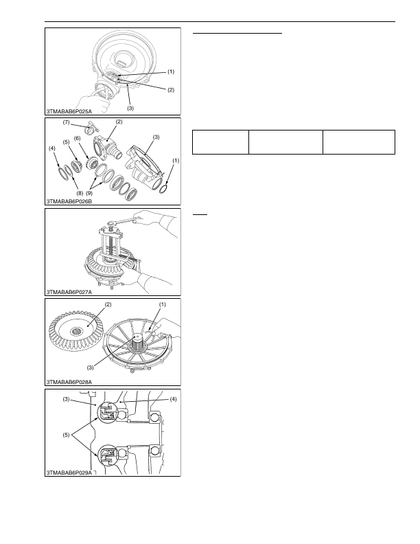
Bevel Gear Case and Gears
1. Remove the axle case support (7).
(except L3560 and L4060)
2. Remove the external snap ring (1).
3. Tap the bevel gear case (2) and separate it from the front gear
case (3).
4. Remove the internal snap ring (4).
5. Remove the bevel gears (5), (6) with ball bearings, and shims
(8).
(When reassembling)
• Install the shims (8) to their original position.
• Install the oil seal (9) of bevel gear case, noting its direction.
9Y1210824FAS0018US0
Axle
1. Remove the bearing with a special use puller set (Code No.
07916-09032).
2. Remove the bevel gear (2).
3. Remove the collar (1).
4. Tap out the axle (3).
(When reassembling)
• Install the oil seal (5) of axle flange (4), noting its direction as
shown in the figure below.
9Y1210824FAS0019US0
Tightening torque
Axle case support
mounting screw
128 to 142 N·m
13.0 to 14.5 kgf·m
94.1 to 104 lbf·ft
(1) External Snap Ring
(2) Bevel Gear Case
(3) Front Gear Case
(4) Internal Snap Ring
(5) Bevel Gear
(6) Bevel Gear
(7) Axle Case Support
(8) Shim
(9) Oil Seal
(1) Collar
(2) Bevel Gear
(3) Axle
(4) Axle Flange
(5) Oil Seal
KiSC issued 03, 2016 A
Detailed Information for Kubota L3560 Owners Manual
Lists of information found in Kubota L3560 Owners Manual - Page 501
- 1. Remove the axle case support (7).
- 2. Remove the external snap ring (1).
- 3. Tap the bevel gear case (2) and separate it from the front gear case (3).
- 4. Remove the internal snap ring (4).
- 5. Remove the bevel gears (5), (6) with ball bearings, and shims (8).
- 1. Remove the bearing with a special use puller set (Code No.
- 2. Remove the bevel gear (2).
- 3. Remove the collar (1).
- 4. Tap out the axle (3).
- 13.0 to 14.
- Install the shims (8) to their original position.
- Install the oil seal (9) of bevel gear case, noting its direction.
- Install the oil seal (5) of axle flange (4), noting its direction as shown in the figure below.