A: Dimension A: ; Spiral Bevel Pinion Shaft and Differential Gear Assembly; 0.50 to 1.0 mm (0.020 to 0.039 in.)- Page 503
Kubota L3560 Owners Manual
Table of Contents
FRONT AXLE
L3560, L4060, L4760, L5060, L5460, L6060, WSM
6-S13
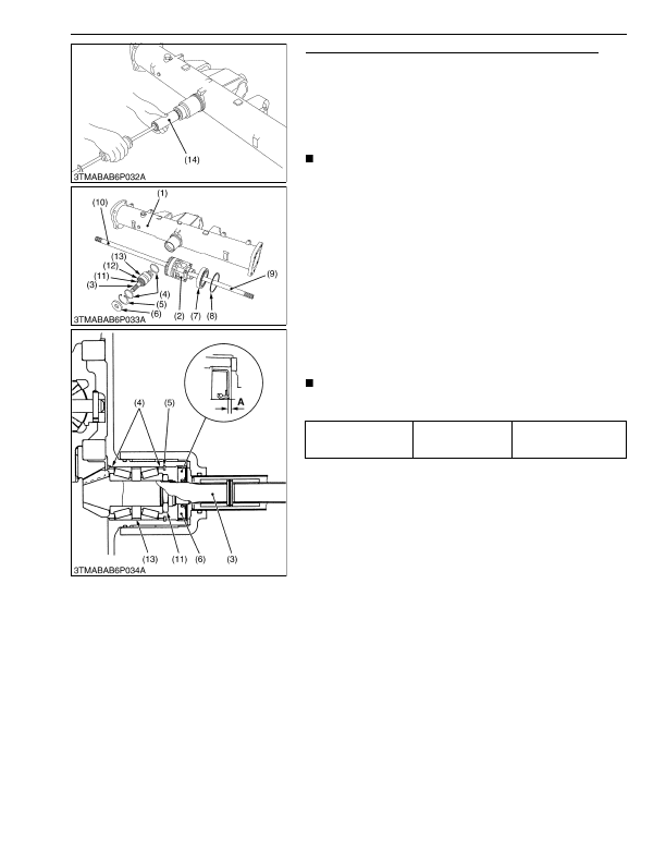
Spiral Bevel Pinion Shaft and Differential Gear Assembly
1. Remove the differential yoke shaft (9), (10) both sides.
2. Remove the oil seal (6) and internal snap ring (5).
3. Remove the collar (4).
4. Remove the spiral bevel pinion shaft (3) by the pinion shaft
remover 1 (14). [L3560 and L4060]
Remove the spiral bevel pinion shaft (3) by the pinion shaft
remover 2 (14) [L4760, L5060, L5460 and L6060]
NOTE
• Refer to G-66 for the pinion shaft remover 1 and 2.
5. Remove the differential gear assembly (2), ball bearing (7) and
shim (8) from left side of front axle case (1).
6. Remove the stake of lock nut (11), and then remove the lock nut
(11).
7. Remove the taper roller bearings (12).
(When reassembling)
• Replace the lock nut (11) and oil seal (6) with new ones.
• Apply grease to the oil seal (6).
• Install the shims and collars to their original position.
• Install the taper roller bearings correctly, noting their direction
and apply gear oil to them.
• Tighten up the lock nut (11) until the turning force of the spiral
bevel pinion shaft reaches the factory specification.
• When press-fitting an oil seal (6), observe the dimension
"A"
described in the figure.
IMPORTANT
• After adjusting the turning torque stake the lock nut (11)
firmly.
9Y1210824FAS0022US0
Turning torque of spiral
bevel pinion shaft
Factory specification
0.98 to 1.1 N·m
0.10 to 0.12 kgf·m
0.73 to 0.86 lbf·ft
(1) Front Axle Case
(2) Differential Gear Assembly
(3) Spiral Bevel Pinion Shaft
(4) Adjusting Collar
(5) Internal Snap Ring
(6) Oil Seal
(7) Ball Bearing
(8) Shim
(9) Differential Yoke Shaft R.H.
(10) Differential Yoke Shaft L.H.
(11) Lock Nut
(12) Taper Roller Bearing
(13) Collar
(14) Pinion Shaft Remover
A: Dimension A:
0.50 to 1.0 mm (0.020 to 0.039 in.)
KiSC issued 03, 2016 A
Detailed Information for Kubota L3560 Owners Manual
Lists of information found in Kubota L3560 Owners Manual - Page 503
- 1. Remove the differential yoke shaft (9), (10) both sides.
- 2. Remove the oil seal (6) and internal snap ring (5).
- 3. Remove the collar (4).
- 4. Remove the spiral bevel pinion shaft (3) by the pinion shaft remover 1 (14).
- 2. 5.
- 6. Remove the stake of lock nut (11), and then remove the lock nut (11).
- 7. Remove the taper roller bearings (12).
- 1.1 N·m 0.
- 1.0 mm (0.
- Refer to G-66 for the pinion shaft remover 1 and 2.
- Replace the lock nut (11) and oil seal (6) with new ones.
- Apply grease to the oil seal (6).
- Install the shims and collars to their original position.
- Install the taper roller bearings correctly, noting their direction and apply gear oil to them.
- Tighten up the lock nut (11) until the turning force of the spiral bevel pinion shaft reaches the factory specification.
- When press-fitting an oil seal (6), observe the dimension "A" described in the figure.
- After adjusting the turning torque stake the lock nut (11) firmly.