Terminal Name; Connector A (26P Connector) of Wire Harness Side; Color of wiring- Page 679
Kubota L3560 Owners Manual
Table of Contents
ELECTRICAL SYSTEM
L3560, L4060, L4760, L5060, L5460, L6060, WSM
9-S41
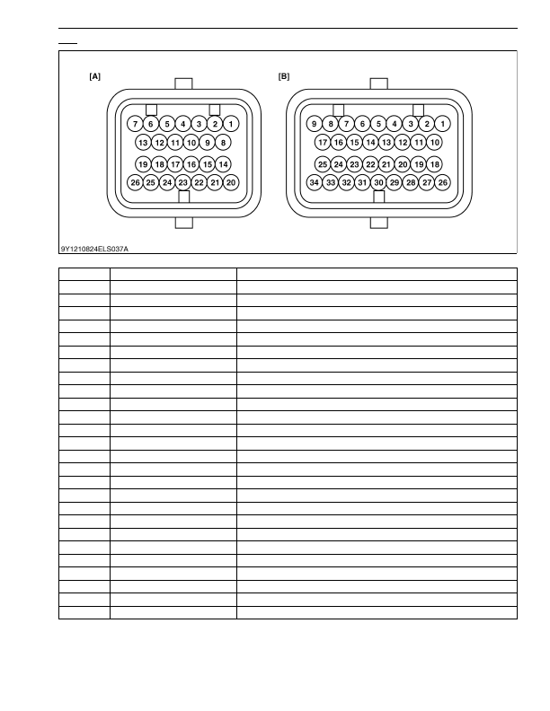
GST
Connector A (26P Connector) of Wire Harness Side
No.
Color of wiring
Terminal Name
1
B
GND (Ground for Circuit Line)
2
W
Return line terminal for proportional reducing valve
3
–
–
4
W
Output terminal for 2nd shift solenoid
5
B/W
Output terminal for 1st shift solenoid
6
P/L
PTO Solenoid
7
R/Y
+12 V (Power Source from Main Switch)
8
R/W
+5 V (Power source for sensor)
9
Y
CAN (H)
10
G
CAN (L)
11
B/W
Starter Relay
12
W/G
DPF Buzzer
13
L
Output terminal for Hi-Lo solenoid
14
B/W
GND (Ground for Sensor)
15
P
TXD (For Check)
16
–
–
17
–
–
18
R
+12 V (Power Source from Battery)
19
Y
Output terminal for range gear shift solenoid
20
–
–
21
V
RXD (For Check)
22
L
Output terminal for proportional reducing valve
23
–
–
24
R
Output terminal for 3rd shift solenoid
25
G
Output terminal for 4th shift solenoid
26
–
–
KiSC issued 03, 2016 A