Hub Plate; Type of compressor; Code No. for circlip- Page 789
Kubota L3560 Owners Manual
Table of Contents
CABIN
L3560, L4060, L4760, L5060, L5460, L6060, WSM
10-S46
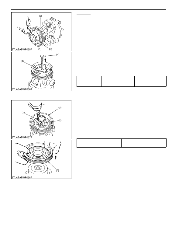
Hub Plate
1. Three stopper bolts (1) are set in stopper magnet clutch (2) at
the position corresponding to the shape of compressor. (See
2. The stopper magnet clutch (2) is hung on hub plate (3) and it is
fixed that the compressor rotates.
3. Remove the magnet clutch mounting screw.
4. Remove the hub plate (3).
5. Remove the shims.
(When reassembling)
• Do not apply grease or oil on the hub plate facing.
• Do not use the magnetic clutch mounting screw again.
• Make sure to turn rotor by hand after assembling and the stator
does not contact with the hub plate.
• Check and adjust the air gap before tight the magnet clutch
mounting screw or nut to the specified torque. (See page
10-S57.)
9Y1210824CAS0075US0
Rotor
1. Remove the circlip (1).
2. Remove the rotor (3).
(When reassembling)
• Do not use the circlip again.
• Assemble the circlip for the tapered side to become outside of
rotor.
• The width of expanding of circlip is set in boss of shaft as a
minimum.
(Reference)
9Y1210824CAS0076US0
Tightening torque
Clutch mounting screw
12.3 to 14.1 N·m
1.25 to 1.44 kgf·m
9.05 to 10.4 lbf·ft
(1) Stopper Bolt
(2) Stopper Magnet Clutch
(3) Hub Plate
(4) Remover Magnet Clutch
Type of compressor
Code No. for circlip
Scroll type
T1065-87450
(1) Circlip
(2) Shim
(3) Rotor
KiSC issued 03, 2016 A
Detailed Information for Kubota L3560 Owners Manual
Lists of information found in Kubota L3560 Owners Manual - Page 789
- 1. Three stopper bolts (1) are set in stopper magnet clutch (2) at the position corresponding to the shape of compressor.
- 72.) 2.
- 3. Remove the magnet clutch mounting screw.
- 4. Remove the hub plate (3).
- 5. Remove the shims.
- 57.) 9Y1210824CAS0075US0 Rotor 1.
- 2. Remove the rotor (3).
- 12.3 to 14.
- 1.25 to 1.
- 9.05 to 10.
- Do not apply grease or oil on the hub plate facing.
- Do not use the magnetic clutch mounting screw again.
- Make sure to turn rotor by hand after assembling and the stator does not contact with the hub plate.
- Check and adjust the air gap before tight the magnet clutch mounting screw or nut to the specified torque.
- Do not use the circlip again.
- Assemble the circlip for the tapered side to become outside of rotor.
- The width of expanding of circlip is set in boss of shaft as a minimum.