ROPS, 3 Point Linkages and Others; Hydraulic Cylinders and Front Loader Control Valve- Page 390
Kubota L3560 Owners Manual
Table of Contents
TRANSMISSION
L3560, L4060, L4760, L5060, L5460, L6060, WSM
3-S71
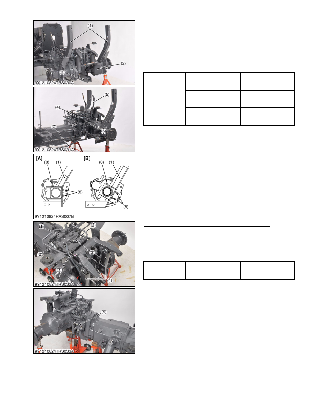
ROPS, 3 Point Linkages and Others
1. Remove the PTO shaft cover (2).
2. Remove the drawbar frame (3).
3. Remove the main gear shift lever (4), range gear shift lever (5)
and four wheel drive lever (6).
4. Disconnect the brake rods (7).
5. Remove the ROPS lower frames (1).
(When reassembling)
9Y1210824TRS0032US0
Hydraulic Cylinders and Front Loader Control Valve
1. Disconnect the hydraulic cylinder hoses (2) and return hoses (3)
at the rear hydraulic block (1).
2. Remove the two pins, and remove the hydraulic cylinders (4).
3. Remove the front loader control valve (5) with front loader
control valve bracket assembly.
9Y1210824TRS0033US0
Tightening torque
Drawbar frame mounting
screw (M12)
78 to 90 N·m
7.9 to 9.2 kgf·m
58 to 66 lbf·ft
Drawbar frame mounting
screw (M14)
167 to 196 N·m
17.0 to 20.0 kgf·m
123 to 144 lbf·ft
ROPS lower frame
mounting screw
167 to 196 N·m
17.0 to 20.0 kgf·m
123 to 144 lbf·ft
(1) ROPS Lower Frame
(2) PTO Shaft Cover
(3) Drawbar Frame
(4) Main Gear Shift Lever
(5) Range Gear Shift Lever
(6) Four Wheel Drive Lever
(7) Brake Rod
(8) Screw (M14 × 30 mm)
[A] L3560
[B] L4060
Tightening torque
Hydraulic cylinder hose
retaining nut
35 to 48 N·m
3.5 to 4.9 kgf·m
26 to 35 lbf·ft
(1) Rear Hydraulic Block
(2) Hydraulic Cylinder Hose
(3) Return Hose
(4) Hydraulic Cylinder
(5) Front Loader Control Valve
KiSC issued 03, 2016 A
Detailed Information for Kubota L3560 Owners Manual
Lists of information found in Kubota L3560 Owners Manual - Page 390
- 1. Remove the PTO shaft cover (2).
- 2. Remove the drawbar frame (3).
- 3. Remove the main gear shift lever (4), range gear shift lever (5) and four wheel drive lever (6).
- 4. Disconnect the brake rods (7).
- 5. Remove the ROPS lower frames (1).
- 1. Disconnect the hydraulic cylinder hoses (2) and return hoses (3) at the rear hydraulic block (1).
- 2. Remove the two pins, and remove the hydraulic cylinders (4).
- 3. Remove the front loader control valve (5) with front loader control valve bracket assembly.
- 7.9 to 9.
- 17.0 to 20.
- 17.0 to 20.
- 3.5 to 4.