Shuttle Shaft- Page 386
Kubota L3560 Owners Manual
Table of Contents
TRANSMISSION
L3560, L4060, L4760, L5060, L5460, L6060, WSM
3-S67
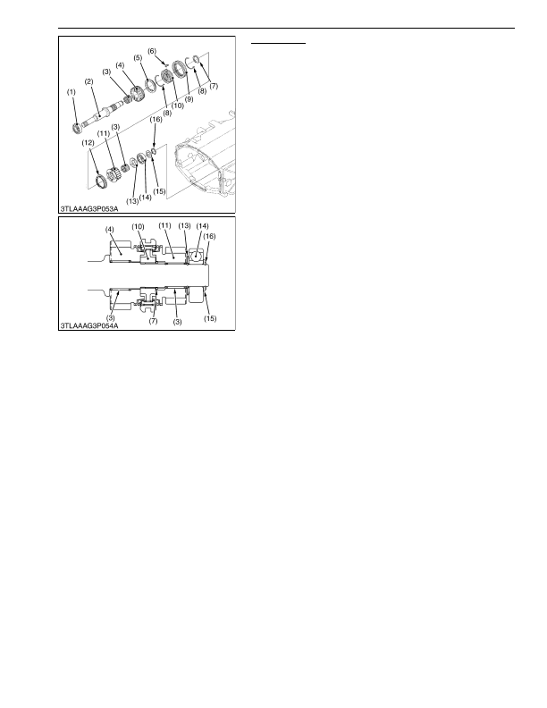
Shuttle Shaft
1. Remove the external snap ring (16) and collar (15).
2. Draw out the bearing (14) with the bearing puller.
3. Remove the thrust collar (13), 18T gear (11) and synchronizer
ring (12).
4. Remove the external snap ring (7), and remove the hub (10)
with shifter (9) and synchronizer ring (5).
5. Remove the 22T gear (4).
(When reassembling)
• Apply enough transmission fluid to the needle bearings (3) and
thrust collar (13).
• Direct the grooved side of the thrust collar (13) to the needle
bearing (3) side.
• Install the external snap ring (7) to the groove of the shuttle shaft
(2) firmly.
• Install the synchronizer keys (6) in the key grooves of the
synchronizer rings (5), (12) firmly.
9Y1210824TRS0026US0
(1) Bearing
(2) Shuttle Shaft
(3) Needle Bearing
(4) 22T Gear (Forward)
(5) Synchronizer Ring
(6) Synchronizer Key
(7) External Snap Ring
(8) Synchronizer Spring
(9) Shifter
(10) Hub
(11) 18T Gear (Reverse)
(12) Synchronizer Ring
(13) Thrust Collar
(14) Bearing
(15) Collar
(16) External Snap Ring
KiSC issued 03, 2016 A
Detailed Information for Kubota L3560 Owners Manual
Lists of information found in Kubota L3560 Owners Manual - Page 386
- 1. Remove the external snap ring (16) and collar (15).
- 2. Draw out the bearing (14) with the bearing puller.
- 3. Remove the thrust collar (13), 18T gear (11) and synchronizer ring (12).
- 4. Remove the external snap ring (7), and remove the hub (10) with shifter (9) and synchronizer ring (5).
- 5. Remove the 22T gear (4).
- Apply enough transmission fluid to the needle bearings (3) and thrust collar (13).
- Direct the grooved side of the thrust collar (13) to the needle bearing (3) side.
- Install the external snap ring (7) to the groove of the shuttle shaft (2) firmly.
- Install the synchronizer keys (6) in the key grooves of the synchronizer rings (5), (12) firmly.