Rear Axle; Brake Case; Rear Hydraulic Block and Lift Arm Support- Page 391
Kubota L3560 Owners Manual
Table of Contents
TRANSMISSION
L3560, L4060, L4760, L5060, L5460, L6060, WSM
3-S72
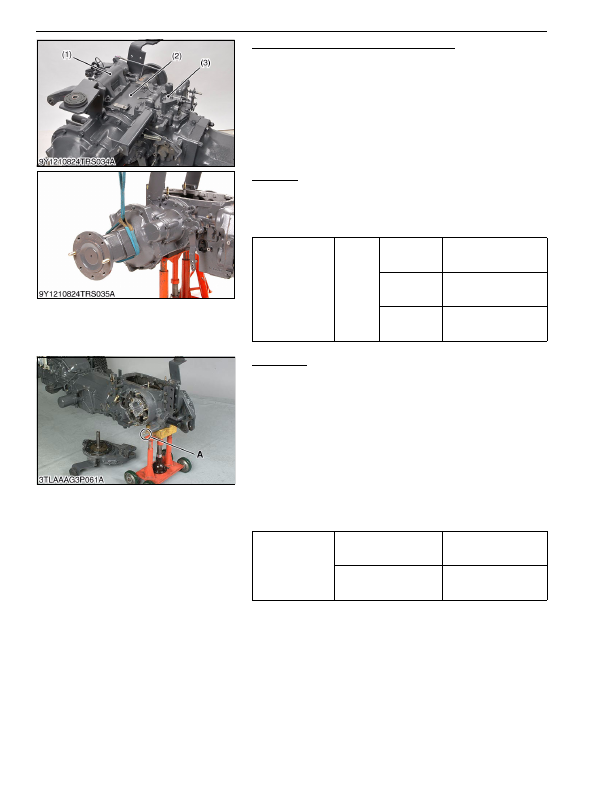
Rear Hydraulic Block and Lift Arm Support
1. Remove the rear hydraulic block (3), cover (2) and lift arm
support (1) as a unit.
(When reassembling)
• Apply liquid gasket (Three Bond 1208C or equivalent) to joint
face of the differential case and cover (2).
9Y1210824TRS0034US0
Rear Axle
1. Separate the rear axle case from brake case.
(When reassembling)
• Apply liquid gasket (Three Bond 1208C or equivalent) to joint
face of the rear axle and brake case.
9Y1210824TRS0035US0
Brake Case
1. Remove the range gear shift lever fulcrum screw.
2. Remove the brake case mounting screws and nuts.
3. Separate the brake case, tapping the brake case lever lightly.
(When reassembling)
• Apply grease to the steel ball seats. (Do not grease
excessively.)
• Apply liquid gasket (Three Bond 1208C or equivalent) to joint
face of the brake cae and transmission case.
• Apply liquid lock to the fulcrum screw.
• Be sure to apply liquid gasket to
"A"
position.
• Be sure to fix the brake cam and cam plate.
• Before installing the brake case to the transmission case, install
the cam plate to the transmission case.
9Y1210824TRS0036US0
(1) Lift Arm Support
(2) Cover
(3) Rear Hydraulic Block
Tightening torque
Rear axle
case
mounting
screw
and nut
M10 screw
48 to 55 N·m
4.9 to 5.7 kgf·m
36 to 41 lbf·ft
M10 nut (9T)
(Except
L3560)
61 to 70 N·m
6.2 to 7.2 kgf·m
45 to 52 lbf·ft
M12 screw
(Except
L3560)
78 to 90 N·m
7.9 to 9.2 kgf·m
58 to 66 lbf·ft
Tightening torque
Brake case mounting screw
and nut
78 to 90 N·m
7.9 to 9.2 kgf·m
58 to 66 lbf·ft
Fulcrum screw
40 to 44 N·m
4.0 to 4.5 kgf·m
29 to 32 lbf·ft
KiSC issued 03, 2016 A
Detailed Information for Kubota L3560 Owners Manual
Lists of information found in Kubota L3560 Owners Manual - Page 391
- 1. Remove the rear hydraulic block (3), cover (2) and lift arm support (1) as a unit.
- 1. Separate the rear axle case from brake case.
- 1. Remove the range gear shift lever fulcrum screw.
- 2. Remove the brake case mounting screws and nuts.
- 3. Separate the brake case, tapping the brake case lever lightly.
- 4.9 to 5.
- 6.2 to 7.
- 7.9 to 9.
- 7.9 to 9.
- 4.0 to 4.
- Apply liquid gasket (Three Bond 1208C or equivalent) to joint face of the differential case and cover (2).
- Apply liquid gasket (Three Bond 1208C or equivalent) to joint face of the rear axle and brake case.
- Apply grease to the steel ball seats.
- Apply liquid gasket (Three Bond 1208C or equivalent) to joint face of the brake cae and transmission case.
- Apply liquid lock to the fulcrum screw.
- Be sure to apply liquid gasket to "A" position.
- Be sure to fix the brake cam and cam plate.
- Before installing the brake case to the transmission case, install the cam plate to the transmission case.