Rear Axle; Hydraulic Cylinders and Front Loader Control Valve; Rear Hydraulic Block and Lift Arm Support- Page 409
Kubota L3560 Owners Manual
Table of Contents
TRANSMISSION
L3560, L4060, L4760, L5060, L5460, L6060, WSM
3-S90
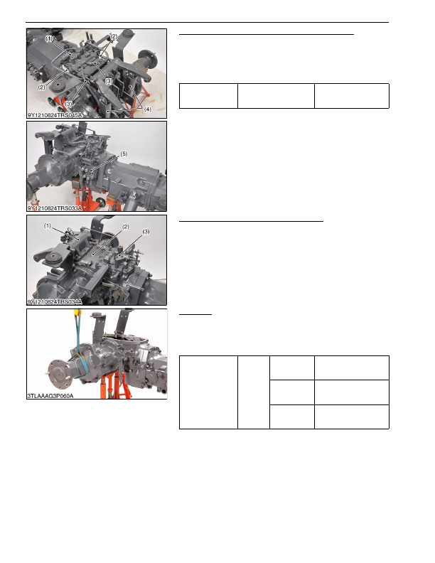
Hydraulic Cylinders and Front Loader Control Valve
1. Disconnect the hydraulic cylinder hoses (2) and return hoses (3)
at the rear hydraulic block (1).
2. Remove the two pins, and remove the hydraulic cylinders (4).
3. Remove the front loader control valve (5) with front loader
control valve bracket assembly.
9Y1210824TRS0071US0
Rear Hydraulic Block and Lift Arm Support
1. Remove the rear hydraulic block (3), cover (2) and lift arm
support (1) as a unit.
(When reassembling)
• Apply liquid gasket (Three Bond 1208C or equivalent) to joint
face of the differential case and cover (2).
9Y1210824TRS0034US0
Rear Axle
1. Separate the rear axle case from brake case.
(When reassembling)
• Apply liquid gasket (Three Bond 1208C or equivalent) to joint
face of the rear axle and brake case.
9Y1210824TRS0072US0
Tightening torque
Hydraulic cylinder hose
retaining nut
35 to 48 N·m
3.5 to 4.9 kgf·m
26 to 35 lbf·ft
(1) Rear Hydraulic Block
(2) Hydraulic Cylinder Hose
(3) Return Hose
(4) Hydraulic Cylinder
(5) Front Loader Control Valve
(1) Lift Arm Support
(2) Cover
(3) Rear Hydraulic Block
Tightening torque
Rear axle
case
mounting
screw
and nut
M10 screw
48 to 55 N·m
4.9 to 5.7 kgf·m
36 to 41 lbf·ft
M10 nut (9T)
(Except
L3560)
61 to 70 N·m
6.2 to 7.2 kgf·m
45 to 52 lbf·ft
M12 screw
(Except
L3560)
78 to 90 N·m
7.9 to 9.2 kgf·m
58 to 66 lbf·ft
KiSC issued 03, 2016 A
Detailed Information for Kubota L3560 Owners Manual
Lists of information found in Kubota L3560 Owners Manual - Page 409
- 1. Disconnect the hydraulic cylinder hoses (2) and return hoses (3) at the rear hydraulic block (1).
- 2. Remove the two pins, and remove the hydraulic cylinders (4).
- 3. Remove the front loader control valve (5) with front loader control valve bracket assembly.
- 1. Remove the rear hydraulic block (3), cover (2) and lift arm support (1) as a unit.
- 1. Separate the rear axle case from brake case.
- 3.5 to 4.
- 4.9 to 5.
- 6.2 to 7.
- 7.9 to 9.
- Apply liquid gasket (Three Bond 1208C or equivalent) to joint face of the differential case and cover (2).
- Apply liquid gasket (Three Bond 1208C or equivalent) to joint face of the rear axle and brake case.