(3) Transmission Case; Hydraulic Pipe; Rear Wheel- Page 408
Kubota L3560 Owners Manual
Table of Contents
TRANSMISSION
L3560, L4060, L4760, L5060, L5460, L6060, WSM
3-S89
(3) Transmission Case
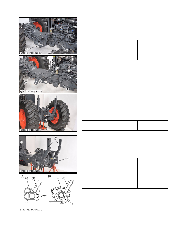
Hydraulic Pipe
1. Remove the front loader pipes (2) and main delivery pipe (1).
2. Remove the left and right brake rods.
3. Disconnect the suction pipe (3).
4. Remove the GST delivery pipe (5) and PTO delivery pipe (4).
(When reassembling)
9Y1210824TRS0052US0
Rear Wheel
1. Place disassembling stand under the transmission case, and
support it with a jack.
2. Remove the rear wheels.
3. After removing the rear wheels, support it at both sides of rear
axle by stands.
(When reassembling)
9Y1210824TRS0069US0
ROPS, 3 Point Linkages and Others
1. Remove the PTO shaft cover (2).
2. Remove the drawbar frame (3).
3. Remove the ROPS lower frames (1).
4. Remove the four wheel drive lever.
(When reassembling)
9Y1210824TRS0070US0
Tightening torque
Joint bolt for main delivery
pipe
118 to 137 N·m
12.0 to 14.0 kgf·m
86.8 to 101 lbf·ft
Joint bolt for PTO delivery
pipe
35 to 39 N·m
3.5 to 4.0 kgf·m
26 to 28 lbf·ft
(1) Main Delivery Pipe
(2) Front Loader Pipe
(3) Suction Pipe
(4) PTO Delivery Pipe
(5) GST Delivery Pipe
Tightening torque
Rear wheel mounting
screw and nut
220 N·m
22 kgf·m
160 lbf·ft
Tightening torque
Drawbar frame mounting
screw (M12)
78 to 90 N·m
7.9 to 9.2 kgf·m
58 to 66 lbf·ft
Drawbar frame mounting
screw (M14)
167 to 196 N·m
17.0 to 20.0 kgf·m
123 to 144 lbf·ft
ROPS lower frame
mounting screw
167 to 196 N·m
17.0 to 20.0 kgf·m
123 to 144 lbf·ft
(1) ROPS Lower Frame
(2) PTO Shaft Cover
(3) Drawbar Frame
(4) Screw (M14 × 30 mm)
[A] L3560
[B] L4060, L4760, L5060
KiSC issued 03, 2016 A
Detailed Information for Kubota L3560 Owners Manual
Lists of information found in Kubota L3560 Owners Manual - Page 408
- 1. Remove the front loader pipes (2) and main delivery pipe (1).
- 2. Remove the left and right brake rods.
- 3. Disconnect the suction pipe (3).
- 4. Remove the GST delivery pipe (5) and PTO delivery pipe (4).
- 1. Place disassembling stand under the transmission case, and support it with a jack.
- 2. Remove the rear wheels.
- 3. After removing the rear wheels, support it at both sides of rear axle by stands.
- 1. Remove the PTO shaft cover (2).
- 2. Remove the drawbar frame (3).
- 3. Remove the ROPS lower frames (1).
- 4. Remove the four wheel drive lever.
- 12.0 to 14.
- 86.8 to 101 lbf·ft Joint bolt for PTO delivery pipe 35 to 39 N·m 3.
- 4.0 kgf·m 26 to 28 lbf·ft (1) Main Delivery Pipe (2) Front Loader Pipe (3) Suction Pipe (4) PTO Delivery Pipe (5) GST Delivery Pipe Tightening torque Rear wheel mounting screw and nut 220 N·m 22 kgf·m 160 lbf·ft Tightening torque Drawbar frame mounting screw (M12) 78 to 90 N·m 7.
- 9.2 kgf·m 58 to 66 lbf·ft Drawbar frame mounting screw (M14) 167 to 196 N·m 17.
- 17.0 to 20.