Shaft Assemblies; Disassembling PTO Clutch; GST Clutch Discs- Page 405
Kubota L3560 Owners Manual
Table of Contents
TRANSMISSION
L3560, L4060, L4760, L5060, L5460, L6060, WSM
3-S86
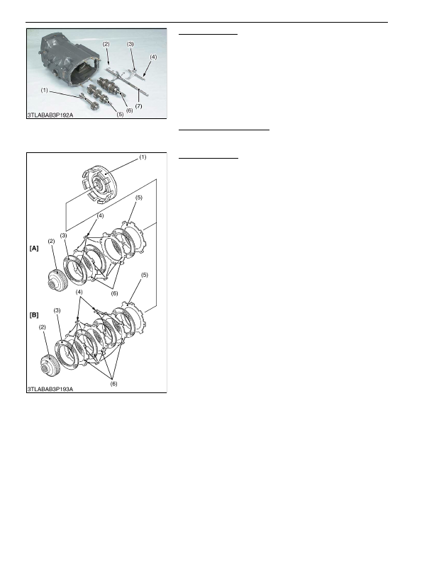
Shaft Assemblies
1. Pull out the sub-range shift rod (4) and remove the shift fork (3).
2. Remove the external snap ring (2) which is located at rear side
of the mid case.
3. Draw out the shaft assemblies (1), (5), (6) and shuttle fork rod
(7).
9Y1210824TRS0064US0
Disassembling PTO Clutch
• See page 3-S68.
9Y1210824TRS0065US0
GST Clutch Discs
1. Remove the clutch hub (2), clutch disc (3) and steel plate (5), (6)
from clutch case (1).
(When reassembling)
• Assemble the two (L3560) or three (L4060, L4760, L5060) steel
plates (6) with plug rubbers (4) to the front side, one steel plate
(5) without plug rubber to the piston side. (Steel plate (5), (6) are
used same part.)
• Do not pile up the plug rubber (4) portion on steel plates (6)
while reassembling as shown in the figure.
9Y1210824TRS0066US0
(1) Reverse Gear Shaft
(2) External Snap Ring
(3) Shift Fork
(4) Sub-range Shift Fork Rod
(5) Shuttle Gear Shaft
(6) Shuttle Shaft
(7) Shuttle Fork Rod
(1) Clutch Case
(2) Clutch Hub
(3) Clutch Disc
(Three pieces for L3560,
four pieces for L4060, L4760,
L5060)
(4) Plug Rubber
(5) Steel Plate without Plug Rubber
(6) Steel Plate with Plug Rubber
(Two pieces for L3560,
three pieces for L4060, L4760,
L5060)
[A] L3560
[B] L4060, L4760, L5060
KiSC issued 03, 2016 A
Detailed Information for Kubota L3560 Owners Manual
Lists of information found in Kubota L3560 Owners Manual - Page 405
- 1. Pull out the sub-range shift rod (4) and remove the shift fork (3).
- 2. Remove the external snap ring (2) which is located at rear side of the mid case.
- 3. Draw out the shaft assemblies (1), (5), (6) and shuttle fork rod (7).
- 68. 9Y1210824TRS0065US0 GST Clutch Discs 1.
- See page 3-S68.
- Assemble the two (L3560) or three (L4060, L4760, L5060) steel plates (6) with plug rubbers (4) to the front side, one steel plate (5) without plug rubber to the piston side.
- Do not pile up the plug rubber (4) portion on steel plates (6) while reassembling as shown in the figure.