Differential Gear Assembly; Disassembling Differential Gears- Page 414
Kubota L3560 Owners Manual
Table of Contents
TRANSMISSION
L3560, L4060, L4760, L5060, L5460, L6060, WSM
3-S95
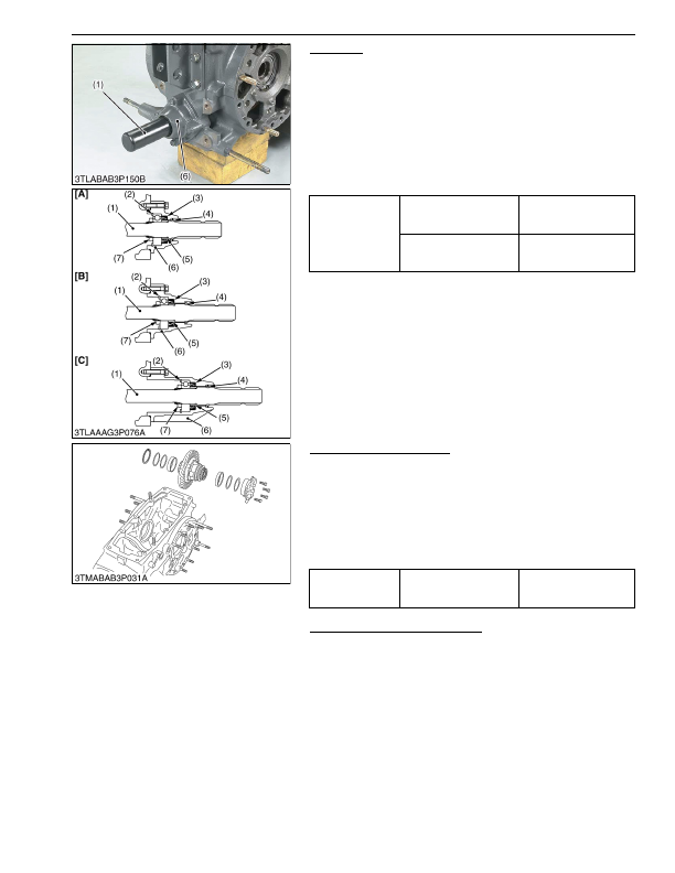
PTO Shaft
1. Remove the PTO shaft cover.
2. Remove the bearing case mounting screws, and draw out the
PTO shaft (1) with bearing case (6).
3. Remove the internal snap ring (2).
4. Top out the PTO shaft (1) to the front.
(When reassembling)
• If the lock nut (7) was removed, replace it with a new one. After
replacing, be sure to stake it firmly.
• Install the slinger (4) firmly.
• Apply grease to the oil seal (3) and install it, noting its direction.
9Y1210824TRS0076US0
Differential Gear Assembly
1. Remove the differential support, noting the number of left shims.
2. Remove the differential gear assembly, noting the number of
right shims.
(When reassembling)
• Check the spiral bevel gear for wear or damage. If it is no longer
serviceable, replace it. Then, also replace the spiral bevel
pinion.
• Use same number of shims as before disassembling.
9Y1210824TRS0077US0
Disassembling Differential Gears
• See page 3-S76.
9Y1210824TRS0078US0
Tightening torque
Lock nut
150 to 190 N·m
15 to 20 kgf·m
110 to 140 lbf·ft
Bearing case mounting
screw
24 to 27 N·m
2.4 to 2.8 kgf·m
18 to 20 lbf·ft
(1) PTO Shaft
(2) Internal Snap Ring
(3) Oil Seal
(4) Slinger
(5) Oil Seal Collar
(6) Bearing Case
(7) Lock Nut
[A] L3560
[B] L4060, L4760
[C] L5060
Tightening torque
Differential support
mounting screw
48 to 55 N·m
4.9 to 5.7 kgf·m
36 to 41 lbf·ft
KiSC issued 03, 2016 A
Detailed Information for Kubota L3560 Owners Manual
Lists of information found in Kubota L3560 Owners Manual - Page 414
- 1. Remove the PTO shaft cover.
- 2. Remove the bearing case mounting screws, and draw out the PTO shaft (1) with bearing case (6).
- 3. Remove the internal snap ring (2).
- 4. Top out the PTO shaft (1) to the front.
- 1. Remove the differential support, noting the number of left shims.
- 2. Remove the differential gear assembly, noting the number of right shims.
- 76. 9Y1210824TRS0078US0 Tightening torque Lock nut 150 to 190 N·m 15 to 20 kgf·m 110 to 140 lbf·ft Bearing case mounting screw 24 to 27 N·m 2.
- 2.8 kgf·m 18 to 20 lbf·ft (1) PTO Shaft (2) Internal Snap Ring (3) Oil Seal (4) Slinger (5) Oil Seal Collar (6) Bearing Case (7) Lock Nut [A] L3560 [B] L4060, L4760 [C] L5060 Tightening torque Differential support mounting screw 48 to 55 N·m 4.
- If the lock nut (7) was removed, replace it with a new one.
- Install the slinger (4) firmly.
- Apply grease to the oil seal (3) and install it, noting its direction.
- Check the spiral bevel gear for wear or damage.
- Use same number of shims as before disassembling.
- See page 3-S76.