(2) Mid Case; Charge Relief Valve; Hydraulic Pipe- Page 430
Kubota L3560 Owners Manual
Table of Contents
TRANSMISSION
L3560, L4060, L4760, L5060, L5460, L6060, WSM
3-S111
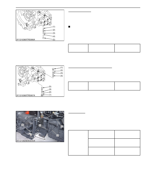
Charge Relief Valve
1. Remove the hex. socket head plug (5).
2. Remove the spring guide (3), shim (4), spring (2) and valve
poppet (1).
(When reassembling)
NOTE
• Install valve component, noting the number of shims (4) in
the charge relief valve.
• Be careful not to damage the O-ring.
• When replacing the valves, check and adjust the setting
pressure. (See page 3-S32.)
9Y1210824TRS0110US0
Check and High Pressure Relief Valve
1. Remove the hex. socket head plug (1) and remove the spring
(3) and relief valve assembly (4), (5).
(When reassembling)
• Be careful not to damage the O-ring on the plug.
9Y1210824TRS0111US0
(2) Mid Case
Hydraulic Pipe
1. Remove the front loader pipes (4).
2. Disconnect the suction hose (1) and suction pipe (6).
3. Remove the main delivery pipe (3), power steering delivery pipe
(2) and delivery pipe (5).
(When reassembling)
9Y1210824ENS0023US0
Tightening torque
Hex. socket head plug of
charge relief valve
49 to 59 N·m
5.0 to 6.0 kgf·m
37 to 43 lbf·ft
(1) Valve Poppet
(2) Spring
(3) Spring Guide
(4) Shim
(5) Hex.Socket Head Plug
Tightening torque
Hex. Socket head plug of
check and high pressure
relief valve
59 to 78 N·m
6.1 to 7.9 kgf·m
44 to 57 lbf·ft
(1) Plug
(2) O-ring
(3) Spring
(4) Check and High Pressure Relief
Valve Assembly (Forward)
(5) Check and High Pressure Relief
Valve Assembly (Reverse)
Tightening torque
Front loader pipe retaining
nut
90.0 to 108 N·m
9.18 to 11.0 kgf·m
66.4 to 79.6 lbf·ft
Joint bolt for main delivery
pipe
40 to 49 N·m
4.0 to 4.9 kgf·m
29 to 36 lbf·ft
Joint bolt for delivery pipe
40 to 49 N·m
4.0 to 4.9 kgf·m
29 to 36 lbf·ft
(1) Suction Hose
(2) Power Steering Delivery Pipe
(3) Main Delivery Pipe
(4) Front Loader Pipe
(5) Delivery Pipe
(6) Suction Pipe
KiSC issued 03, 2016 A
Detailed Information for Kubota L3560 Owners Manual
Lists of information found in Kubota L3560 Owners Manual - Page 430
- 1. Remove the hex.
- 2. Remove the spring guide (3), shim (4), spring (2) and valve poppet (1).
- 32.) 9Y1210824TRS0110US0 Check and High Pressure Relief Valve 1.
- 1. Remove the front loader pipes (4).
- 2. Disconnect the suction hose (1) and suction pipe (6).
- 3. Remove the main delivery pipe (3), power steering delivery pipe (2) and delivery pipe (5).
- 5.0 to 6.
- 6.1 to 7.
- 9.18 to 11.
- 66.4 to 79.
- 4.0 to 4.
- 4.0 to 4.
- Install valve component, noting the number of shims (4) in the charge relief valve.
- Be careful not to damage the O-ring.
- When replacing the valves, check and adjust the setting pressure.
- Be careful not to damage the O-ring on the plug.