(3) Transmission Case; Mid Case Bearing Holder with Gears; Disassembling PTO Clutch- Page 433
Kubota L3560 Owners Manual
Table of Contents
TRANSMISSION
L3560, L4060, L4760, L5060, L5460, L6060, WSM
3-S114
Mid Case Bearing Holder with Gears
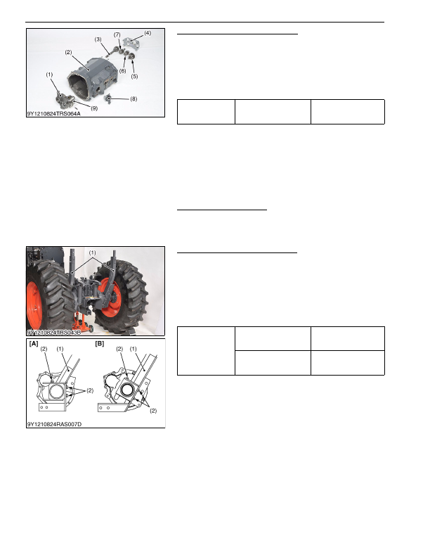
1. Remove the mid case bearing holder 1 (4).
2. Remove the gear shafts (3), (7), (6), (5).
3. Remove the mid case bearing holder 2 (1) with PTO clutch (9).
(When reassembling)
• Tap in the mid case bearing holder (1), (4) with plastic hummer
until contact to mid case, and then tighten the screws to
specified torque.
9Y1210824TRS0115US0
Disassembling PTO Clutch
• See page 3-S68.
9Y1210824TRS0065US0
(3) Transmission Case
Rear Wheel and ROPS Lower Frame
1. Place disassembling stand under the transmission case, and
support it with a jack.
2. Remove the rear wheels.
3. After removing the rear wheels, support it at both sides of rear
axle by stands.
4. Remove the ROPS lower frame mounting screws (2).
5. Remove the ROPS lower frames (1).
(When reassembling)
9Y1210824TRS0116US0
Tightening torque
Mid case bearing holder
mounting screw
48 to 55 N·m
4.9 to 5.7 kgf·m
36 to 41 lbf·ft
(1) Mid Case Bearing Holder 2
(2) Mid Case
(3) 20T Gear Shaft (L5460, L6060)
22T Gear Shaft (L3560, L4060,
L4760)
(4) Mid Case Bearing Holder 1
(5) 24T Gear Shaft (L3560)
25T Gear Shaft (L4060, L4760)
27T Gear Shaft (L5460, L6060)
(6) 14T Gear Shaft (L5460, L6060)
15T Gear Shaft (L4060, L4760)
15T Gear Shaft (L3560)
(7) 21T Gear Shaft (L3560, L4060,
L4760)
22T Gear Shaft (L5460, L6060)
(8) PTO Clutch Valve
(9) PTO Clutch
Tightening torque
Rear wheel mounting
screw and nut
220 N·m
22 kgf·m
160 lbf·ft
ROPS lower frame
mounting torque
167 to 196 N·m
17.0 to 20.0 kgf·m
123 to 144 lbf·ft
(1) ROPS Lower Frame
(2) Screw (M14 × 30)
[A} L3560
[B} L4060, L4760, L5460, L6060
KiSC issued 03, 2016 A
Detailed Information for Kubota L3560 Owners Manual
Lists of information found in Kubota L3560 Owners Manual - Page 433
- 1. Remove the mid case bearing holder 1 (4).
- 2. Remove the gear shafts (3), (7), (6), (5).
- 3. Remove the mid case bearing holder 2 (1) with PTO clutch (9).
- 68. 9Y1210824TRS0065US0 (3) Transmission Case Rear Wheel and ROPS Lower Frame 1.
- 2. Remove the rear wheels.
- 3. After removing the rear wheels, support it at both sides of rear axle by stands.
- 4. Remove the ROPS lower frame mounting screws (2).
- 5. Remove the ROPS lower frames (1).
- 4.9 to 5.
- 17.0 to 20.
- Tap in the mid case bearing holder (1), (4) with plastic hummer until contact to mid case, and then tighten the screws to specified torque.
- See page 3-S68.