Pressure Switch Resistance; Oil Temperature Sensor Resistance; Proportional Reducing Valve Resistance- Page 688
Kubota L3560 Owners Manual
Table of Contents
ELECTRICAL SYSTEM
L3560, L4060, L4760, L5060, L5460, L6060, WSM
9-S50
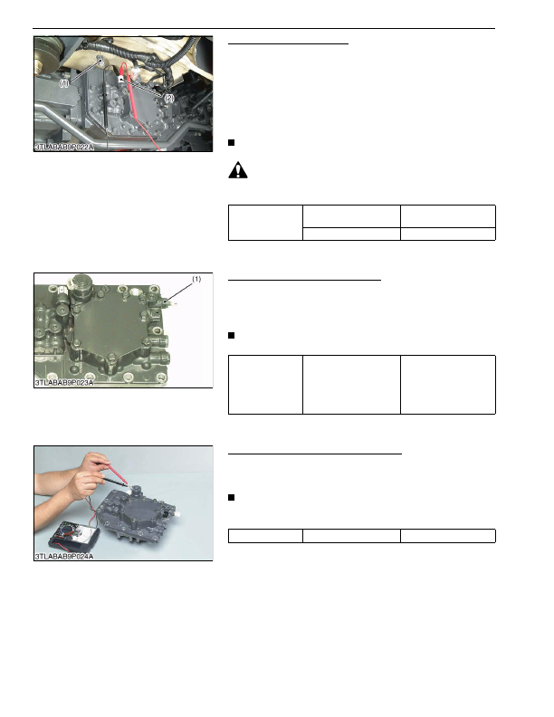
Pressure Switch Resistance
1. Disconnect the pressure switch connector (1).
2. Connect the circuit tester pins to each terminal of pressure
switch (2).
3. Start the engine and depress the clutch pedal.
4. Check the resistance at time when shuttle lever or GST lever is
shifted.
5. It is OK if the resistance comes to have shown in the table
below.
NOTE
• It is not necessary to adjust any kind of mode.
CAUTION
• Be sure to depress the clutch pedal so that the tractor
should not move while shifting each lever.
9Y1210824ELS0044US0
Oil Temperature Sensor Resistance
1. Measure the resistance between the sensor terminals.
2. It is OK if the resistance value approximates to the value shown
in the table below.
3. If the exists a large difference, replace the sensor.
NOTE
• It is not necessary to adjust any kind of mode.
9Y1210824ELS0045US0
Proportional Reducing Valve Resistance
1. Measure the resistance between the valve terminals.
2. It is OK if the resistance comes to have shown in the table
below.
NOTE
• When replacing the proportional reducing valve be sure to
adjust the mode "F".
9Y1210824ELS0046US0
Resistance between
terminals
When the shuttle lever or
GST lever is shifted
Continuity exists
Both levers are at Neutral
0 Ω
(1) Pressure Switch Connector
(2) Pressure Switch
Resistance
Reference value
16.4 to 21.1 kΩ at −20 °C
(−4 °F)
1.04 to 1.23 kΩ at 40 °C
(104 °F)
0.15 to 0.16 kΩ at 100 °C
(212 °F)
(1) Oil Temperature Sensor
Resistance
Reference value
8 to 9 Ω
KiSC issued 03, 2016 A
Detailed Information for Kubota L3560 Owners Manual
Lists of information found in Kubota L3560 Owners Manual - Page 688
- 1. Disconnect the pressure switch connector (1).
- 2. Connect the circuit tester pins to each terminal of pressure switch (2).
- 3. Start the engine and depress the clutch pedal.
- 4. Check the resistance at time when shuttle lever or GST lever is shifted.
- 5. It is OK if the resistance comes to have shown in the table below.
- 1. Measure the resistance between the sensor terminals.
- 2. It is OK if the resistance value approximates to the value shown in the table below.
- 3. If the exists a large difference, replace the sensor.
- 1. Measure the resistance between the valve terminals.
- 2. It is OK if the resistance comes to have shown in the table below.
- 16.4 to 21.
- 1.04 to 1.
- It is not necessary to adjust any kind of mode.
- Be sure to depress the clutch pedal so that the tractor should not move while shifting each lever.
- It is not necessary to adjust any kind of mode.
- When replacing the proportional reducing valve be sure to adjust the mode "F".