Shift Solenoid Resistance; A: Connector of Solenoid Side- Page 689
Kubota L3560 Owners Manual
Table of Contents
L3560,L4060,L4760,L5060,L5460,L6060
ELECTRICAL SYSTEM
L3560, L4060, L4760, L5060, L5460, L6060, WSM
9-S51
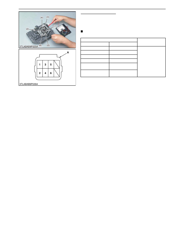
Shift Solenoid Resistance
1. Measure the resistance between each connector terminal and
each valve body.
2. It is OK if the resistance comes to have shown in the table
below.
NOTE
• It is not necessary to adjust any kind of mode.
9Y1210824ELS0047US0
Measuring point
Resistance
Solenoid
Connector terminal
(1) Solenoid 1
1
11 to 15 Ω
(2) Solenoid 2
2
(3) Solenoid 3
3
(4) Solenoid 4
4
(5) Solenoid 5
(Sub- range)
5
(6) Solenoid 6
(Main range)
6
A: Connector of Solenoid Side
KiSC issued 03, 2016 A
Detailed Information for Kubota L3560 Owners Manual
Lists of information found in Kubota L3560 Owners Manual - Page 689
- 1. Measure the resistance between each connector terminal and each valve body.
- 2. It is OK if the resistance comes to have shown in the table below.
- It is not necessary to adjust any kind of mode.