(2) Control Panel (Blower Switch, A/C Switch, Mode Control Dial and Temperature Control Dial); Temperature Control Dial); Blower Switch Connector Voltage- Page 766
Kubota L3560 Owners Manual
Table of Contents
CABIN
L3560, L4060, L4760, L5060, L5460, L6060, WSM
10-S23
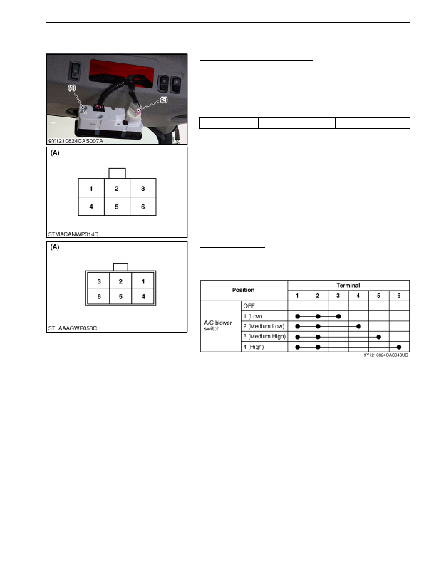
(2) Control Panel (Blower Switch, A/C Switch, Mode Control Dial and
Temperature Control Dial)
Blower Switch Connector Voltage
1. Disconnect the
6P
connector (2) from blower switch.
2. Turn the main switch to
"ON"
position.
3. Measure the voltage with a voltmeter across the connector
terminal
1
and terminal
4
.
4. If the voltage differs from the battery voltage, the wiring harness,
A/C relay, fuse or main switch is faulty.
9Y1210824CAS0051US0
Blower Switch Test
1. Check the continuity through the switch with an ohmmeter.
2. If the continuity specified below are not indicated, the switch is
faulty.
9Y1210824CAS0052US0
Voltage
Terminal
1
– Terminal
4
Approx. battery voltage
(1) Control Panel
(2)
6P
Connector
(A) 6P Connector (Wire Harness
Side)
(A) 6P Connector
(Blower Switch Side)
KiSC issued 03, 2016 A
Detailed Information for Kubota L3560 Owners Manual
Lists of information found in Kubota L3560 Owners Manual - Page 766
- 1. Disconnect the 6P connector (2) from blower switch.
- 2. Turn the main switch to "ON" position.
- 3. Measure the voltage with a voltmeter across the connector terminal 1 and terminal 4 .
- 4. If the voltage differs from the battery voltage, the wiring harness, A/C relay, fuse or main switch is faulty.
- 1. Check the continuity through the switch with an ohmmeter.
- 2. If the continuity specified below are not indicated, the switch is faulty.