(3) Blower Resistor; Temperature Control Dial Checking; A/C Blower Resistor- Page 769
Kubota L3560 Owners Manual
Table of Contents
CABIN
L3560, L4060, L4760, L5060, L5460, L6060, WSM
10-S26
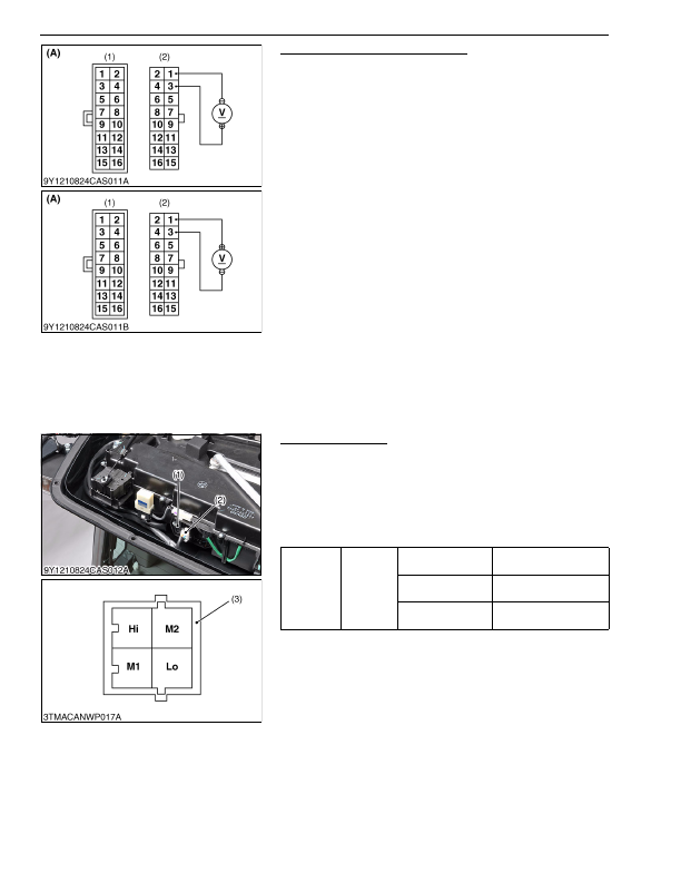
Temperature Control Dial Checking
1. Turn the temperature control dial counterclockwise till it stops
(at
"COOL"
position).
2. Measure the voltage with a voltmeter across the terminal
1
and
terminal
3
. Make the following measurement with the terminals
connected.
3. Turn the main switch to
"ON"
position.
4. Check that an output voltage is approximately 10 V when
turning the temperature control dial clockwise till it stops
(
"WARM"
position).
5. Turn the main switch back to
"OFF"
position.
6. Turn the temperature control dial clockwise till it stops
(
"WARM"
position).
7. Measure the voltage with a voltmeter across the terminal
3
and
terminal
1
. Make the following measurement with the terminals
connected.
8. Turn the main switch to
"ON"
position.
9. Check that an output voltage is approximately 10 V, when
turning the temperature control dial counterclockwise till it stops
(
"COOL"
position).
10. If an output voltage differs from approximately 10 V, the control
panel, wiring harness of fuse is faulty.
9Y1210824CAS0056US0
(3) Blower Resistor
A/C Blower Resistor
1. Remove the outer roof.
2. Disconnect the
4P
connector (2) for A/C blower resistor (1).
3. Measure the resistance with an ohmmeter across terminal
M2
and terminal
Hi
, and across the terminal
M1
and terminal
Hi
,
and across the terminal
Lo
and terminal
Hi
.
4. If the factory specifications are not indicated, A/C blower
resistor is faulty.
9Y1210824CAS0057US0
(1)
16P
Connector (Switch Side)
(2)
16P
Connector (Wire Harness Side)
(A) "COOL" position to "WARM"
position
(B) "WARM" position to "COOL"
position
Resistance
Factory
specifica-
tion
Terminal
Hi
–
Terminal
M2
Approx. 0.22 Ω
Terminal
Hi
–
Terminal
M1
Approx. 0.69 Ω
Terminal
Hi
–
Terminal
Lo
Approx. 1.69 Ω
(1) Blower Resistor
(2)
4P
Connector (Wire Harness Side)
(3)
4P
Connector
(Blower Resistor Side)
KiSC issued 03, 2016 A
Detailed Information for Kubota L3560 Owners Manual
Lists of information found in Kubota L3560 Owners Manual - Page 769
- 1. Turn the temperature control dial counterclockwise till it stops (at "COOL" position).
- 2. Measure the voltage with a voltmeter across the terminal 1 and terminal 3 .
- 3. Turn the main switch to "ON" position.
- 4. Check that an output voltage is approximately 10 V when turning the temperature control dial clockwise till it stops ( "WARM" position).
- 5. Turn the main switch back to "OFF" position.
- 6. Turn the temperature control dial clockwise till it stops ( "WARM" position).
- 7. Measure the voltage with a voltmeter across the terminal 3 and terminal 1 .
- 8. Turn the main switch to "ON" position.
- 9. Check that an output voltage is approximately 10 V, when turning the temperature control dial counterclockwise till it stops ( "COOL" position).
- 1. Remove the outer roof.
- 2. Disconnect the 4P connector (2) for A/C blower resistor (1).
- 3. Measure the resistance with an ohmmeter across terminal M2 and terminal Hi , and across the terminal M1 and terminal Hi , and across the terminal Lo and terminal Hi .
- 4. If the factory specifications are not indicated, A/C blower resistor is faulty.