(2) Mid Case; Hydraulic Pipe; GST Valve Assembly- Page 402
Kubota L3560 Owners Manual
Table of Contents
TRANSMISSION
L3560, L4060, L4760, L5060, L5460, L6060, WSM
3-S83
(2) Mid Case
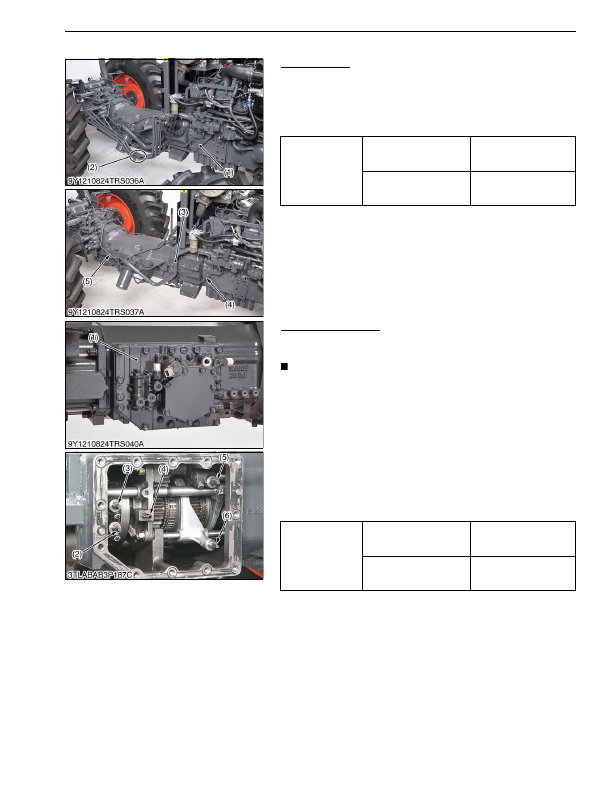
Hydraulic Pipe
1. Remove the front loader pipes (2) and main delivery pipe (1).
2. Remove the left and right brake rods.
3. Disconnect the suction pipe (3).
4. Remove the GST delivery pipe (5) and PTO delivery pipe (4).
(When reassembling)
9Y1210824TRS0052US0
GST Valve Assembly
1. Remove the GST valve (1) with using two jack bolts.
2. Remove the shift pin (2), (3) and (5).
NOTE
• Do not fall down the shift pin while disassembling.
(When reassembling)
• Place the 1-2 (2) and 3-4 shift pins (3) at
neutral
position,
sub-range shift pin (6) at
Hi
position (rearward) and main range
shift pin (5) at
L
position (forward), and then assemble the GST
valve.
• Be sure to match the each shift pin and shift piston.
• Install the GST valve (1) by hand, and then tighten the screws.
Do not use the hummer.
• Apply liquid gasket (Three Bond 1208C or equivalent) to joint
face of the GST valve assembly.
• Replace the pipe (4) with a new one, if damaged.
9Y1210824TRS0060US0
Tightening torque
Joint bolt for main delivery
pipe
118 to 137 N·m
12.0 to 14.0 kgf·m
86.8 to 101 lbf·ft
Joint bolt for PTO delivery
pipe
35 to 39 N·m
3.5 to 4.0 kgf·m
26 to 28 lbf·ft
(1) Main Delivery Pipe
(2) Front Loader Pipe
(3) Suction Pipe
(4) PTO Delivery Pipe
(5) GST Delivery Pipe
Tightening torque
GST valve mounting
screws
43 to 48 N·m
4.3 to 4.9 kgf·m
32 to 35 lbf·ft
Shift pin mounting screw
13 to 14 N·m
1.3 to 1.5 kgf·m
9.4 to 10 lbf·ft
(1) GST Valve
(2) 1-2 Shift Pin
(3) 3-4 Shift Pin
(4) Pipe
(5) Main Range Shift Pin
(6) Sub-range Shift Pin
KiSC issued 03, 2016 A
Detailed Information for Kubota L3560 Owners Manual
Lists of information found in Kubota L3560 Owners Manual - Page 402
- 1. Remove the front loader pipes (2) and main delivery pipe (1).
- 2. Remove the left and right brake rods.
- 3. Disconnect the suction pipe (3).
- 4. Remove the GST delivery pipe (5) and PTO delivery pipe (4).
- 1. Remove the GST valve (1) with using two jack bolts.
- 2. Remove the shift pin (2), (3) and (5).
- 12.0 to 14.
- 86.8 to 101 lbf·ft Joint bolt for PTO delivery pipe 35 to 39 N·m 3.
- 4.0 kgf·m 26 to 28 lbf·ft (1) Main Delivery Pipe (2) Front Loader Pipe (3) Suction Pipe (4) PTO Delivery Pipe (5) GST Delivery Pipe Tightening torque GST valve mounting screws 43 to 48 N·m 4.
- 4.9 kgf·m 32 to 35 lbf·ft Shift pin mounting screw 13 to 14 N·m 1.
- 1.5 kgf·m 9.
- Do not fall down the shift pin while disassembling.
- Place the 1-2 (2) and 3-4 shift pins (3) at neutral position, sub-range shift pin (6) at Hi position (rearward) and main range shift pin (5) at L position (forward), and then assemble the GST valve.
- Be sure to match the each shift pin and shift piston.
- Install the GST valve (1) by hand, and then tighten the screws.
- Apply liquid gasket (Three Bond 1208C or equivalent) to joint face of the GST valve assembly.
- Replace the pipe (4) with a new one, if damaged.