Mid Case Bearing Holder; PTO Clutch Valve; out the bearing holder (2).- Page 404
Kubota L3560 Owners Manual
Table of Contents
TRANSMISSION
L3560, L4060, L4760, L5060, L5460, L6060, WSM
3-S85
PTO Clutch Valve
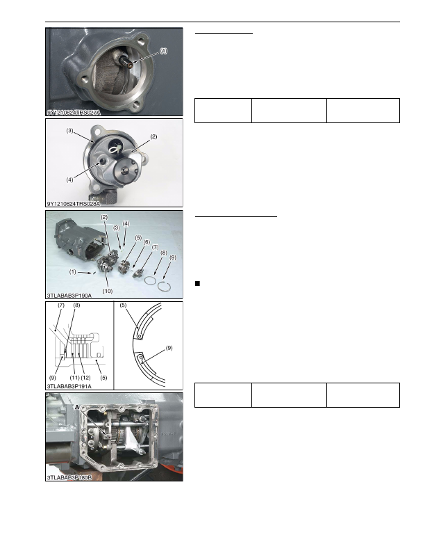
1. Remove the PTO clutch valve (2) as a unit.
2. Pull out the pipe (1).
(When reassembling)
• Apply small amount of grease for the O-ring (3).
• Install the pipe (1) to the hole (4) of the PTO clutch valve (2)
firmly.
• Replace the pipe (1) with a new one.
9Y1210824TRS0023US0
Mid Case Bearing Holder
1. Remove the internal snap ring (9) and remove the disc spring
(8) and clutch input hub (7).
2. Remove the external snap ring (6) and remove the GST clutch
case (5).
3. Remove the mid case bearing holder mounting screws.
4. Remove the bearing holder (2) with PTO clutch (10) by using
two jack bolts.
NOTE
• Be careful not to fly out the ball (4) and spring (3) when pull
out the bearing holder (2).
(When reassembling)
• Tap in bearing holder (2) with plastic hummer until contact to
case, and then tighten the screws to specified torque.
• Assemble the disc spring (8) as shown in the figure.
• Install the internal snap ring (9) to the clutch case (5) as shown
in the figure.
• Make sure the piston moves smoothly when pressure air at 0.29
to 0.39 MPa (3 to 4 kgf/cm
2
, 42 to 57 psi) is sent to clutch pack.
(Air must be sent from hole
"A"
.)
9Y1210824TRS0063US0
Tightening torque
PTO clutch valve mounting
screw
23.5 to 27.4 N·m
2.40 to 27.4 kgf·m
17.4 to 20.2 lbf·ft
(1) Pipe
(2) PTO Clutch Valve
(3) O-ring
(4) Hole
Tightening torque
Mid case bearing holder
mounting screw
48 to 55 N·m
4.9 to 5.7 kgf·m
36 to 41 lbf·ft
(1) PTO Clutch Pipe
(2) Mid Case Bearing Holder
(3) Spring
(4) Ball
(5) Clutch Case
(6) External Snap Ring
(7) Clutch Input Hub
(8) Disc Spring
(9) Internal Snap Ring
(10) PTO Clutch
(11) Clutch Disc
(12) Steel Plate
A: Oil Inlet Port for GST Clutch
KiSC issued 03, 2016 A
Detailed Information for Kubota L3560 Owners Manual
Lists of information found in Kubota L3560 Owners Manual - Page 404
- 1. Remove the PTO clutch valve (2) as a unit.
- 2. Pull out the pipe (1).
- 1. Remove the internal snap ring (9) and remove the disc spring (8) and clutch input hub (7).
- 2. Remove the external snap ring (6) and remove the GST clutch case (5).
- 3. Remove the mid case bearing holder mounting screws.
- 4. Remove the bearing holder (2) with PTO clutch (10) by using two jack bolts.
- 23.5 to 27.
- 2.40 to 27.
- 17.4 to 20.
- 4.9 to 5.
- Apply small amount of grease for the O-ring (3).
- Install the pipe (1) to the hole (4) of the PTO clutch valve (2) firmly.
- Replace the pipe (1) with a new one.
- Be careful not to fly out the ball (4) and spring (3) when pull out the bearing holder (2).
- Tap in bearing holder (2) with plastic hummer until contact to case, and then tighten the screws to specified torque.
- Assemble the disc spring (8) as shown in the figure.
- Install the internal snap ring (9) to the clutch case (5) as shown in the figure.
- Make sure the piston moves smoothly when pressure air at 0.