Separating Mid Case; A: Fork Rod Groove; Separating Mid Case and Transmission Case- Page 403
Kubota L3560 Owners Manual
Table of Contents
TRANSMISSION
L3560, L4060, L4760, L5060, L5460, L6060, WSM
3-S84
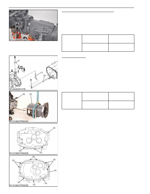
Separating Mid Case and Transmission Case
1. Separate the mid case and transmission case after removing
their mounting screws.
(When reassembling)
• Make sure to insert the PTO shaft to PTO clutch firmly, turning
the PTO shaft.
• Apply liquid gasket (Three Bond 1208C or equivalent) to joint
face of the mid case and transmission case.
9Y1210824TRS0061US0
Separating Mid Case
1. Lift up the shuttle shift arm (1).
2. Separate the mid case (4) from the clutch housing (3) after
removing their mounting screws.
(When reassembling)
• Apply liquid gasket (Three Bond 1208C or equivalent) to joint
face of clutch housing (3) and mid case (4).
• Make sure to apply liquid gasket to elongated grooves (5) on the
mid case face and to those on the lower side of the clutch
housing face.
• When reassembling the shuttle shift arm (1) to the shuttle fork
rod (2), be sure to install it to the groove
"A"
.
9Y1210824TRS0062US0
Tightening torque
Mid case and transmission
case mounting screw
78 to 90 N·m
7.9 to 9.2 kgf·m
58 to 66 lbf·ft
Mid case and transmission
case mounting nut
103 to 117 N·m
10.5 to 12.0 kgf·m
76.0 to 86.7 lbf·ft
Tightening torque
Clutch housing and mid
case mounting screw
78 to 90 N·m
7.9 to 9.2 kgf·m
58 to 66 lbf·ft
Clutch housing and mid
case mounting nut
103 to 117 N·m
10.5 to 12.0 kgf·m
76.0 to 86.7 lbf·ft
(1) Shuttle Shift Arm
(2) Shuttle Fork Rod
(3) Clutch Housing
(4) Mid Case
(5) Elongated Groove
A: Fork Rod Groove
KiSC issued 03, 2016 A
Detailed Information for Kubota L3560 Owners Manual
Lists of information found in Kubota L3560 Owners Manual - Page 403
- 1. Separate the mid case and transmission case after removing their mounting screws.
- 1. Lift up the shuttle shift arm (1).
- 2. Separate the mid case (4) from the clutch housing (3) after removing their mounting screws.
- 7.9 to 9.
- 12.0 kgf·m 76.
- 86.7 lbf·ft Tightening torque Clutch housing and mid case mounting screw 78 to 90 N·m 7.
- 9.2 kgf·m 58 to 66 lbf·ft Clutch housing and mid case mounting nut 103 to 117 N·m 10.
- 12.0 kgf·m 76.
- Make sure to insert the PTO shaft to PTO clutch firmly, turning the PTO shaft.
- Apply liquid gasket (Three Bond 1208C or equivalent) to joint face of the mid case and transmission case.
- Apply liquid gasket (Three Bond 1208C or equivalent) to joint face of clutch housing (3) and mid case (4).
- Make sure to apply liquid gasket to elongated grooves (5) on the mid case face and to those on the lower side of the clutch housing face.
- When reassembling the shuttle shift arm (1) to the shuttle fork rod (2), be sure to install it to the groove "A" .