HST Proportional Valve (Forward and Reverse); attention to the color of the connector to ensure correct; A: Connector of Proportional Side- Page 696
Kubota L3560 Owners Manual
Table of Contents
ELECTRICAL SYSTEM
L3560, L4060, L4760, L5060, L5460, L6060, WSM
9-S58
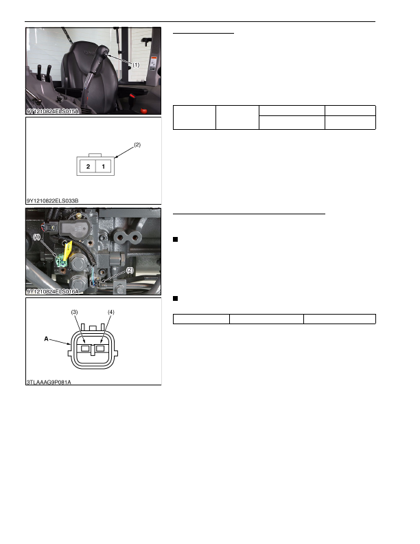
Throttle-Up Switch
1. Remove the side cover.
2. Disconnect the
2P
connector of throttle-up switch (1).
3. Measure the continuity with an ohmmeter across the switch
terminals.
4. If it does not conduct or any value is indicated when the switch
is pushed, the switch is faulty.
5. If infinity is not indicated when the switch is released, the switch
is faulty.
9Y1210824ELS0055US0
HST Proportional Valve (Forward and Reverse)
1. Remove the cover.
2. Disconnect the
2P
connector of the proportional valve (1), (2).
IMPORTANT
• In installing the connector of the proportional valve, pay
attention to the color of the connector to ensure correct
installation.
3. Measure the resistance between terminal
1
(3) and
2
(4).
4. It is OK if the resistance comes to have shown in the table
below.
NOTE
• When replacing the sensor, be sure to adjust the mode "K".
9Y1210824ELS0056US0
Resistance
(Across switch
terminal)
Reference
value
When switch is pushed
0 Ω
When switch is released Infinity
(1) Throttle-Up Switch
(2) Connector of Switch Side
Resistance
Terminal
1
– Terminal
2
Approx. 3.1 kΩ
(1) Proportional Valve Connector
(Green)
(2) Proportional Valve Connector
(Gray)
(3) Terminal
1
(4) Terminal
2
A: Connector of Proportional Side
KiSC issued 03, 2016 A
Detailed Information for Kubota L3560 Owners Manual
Lists of information found in Kubota L3560 Owners Manual - Page 696
- 1. Remove the side cover.
- 2. Disconnect the 2P connector of throttle-up switch (1).
- 3. Measure the continuity with an ohmmeter across the switch terminals.
- 4. If it does not conduct or any value is indicated when the switch is pushed, the switch is faulty.
- 5. If infinity is not indicated when the switch is released, the switch is faulty.
- 1. Remove the cover.
- 2. Disconnect the 2P connector of the proportional valve (1), (2).
- 3. Measure the resistance between terminal 1 (3) and 2 (4).
- 4. It is OK if the resistance comes to have shown in the table below.
- In installing the connector of the proportional valve, pay attention to the color of the connector to ensure correct installation.
- When replacing the sensor, be sure to adjust the mode "K".